Any network diagram is based on a diagram template which holds the configuration properties defining the content (rule and layout definitions) and presentation (diagram layer definition) of network diagrams. The diagram layer definition configured on a template specifies the representation of the layers under any network diagram layer related to this template. It is the set of layer and labeling properties specified for each layer that composes these network diagram layers.
When combining subtype group layers with complex symbol and label settings for each layer, the diagram template layer definition can become weighty. Then, the more weighty it is, the more it will penalize display loading of diagrams at their opening and increase memory footprint on the server. This article gives you recommendations to optimize layer definitions on your diagram templates.
Diagram template layer definition
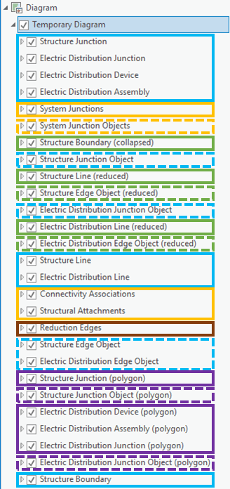
Without any customization on your part, any diagram template is created with a default diagram layer definition. This means that all diagrams based on the new template display in a network diagram composite layer with same basic default settings for a fixed set of layers. These default layers are shown below:

They are intended to represent:
- network features from each source feature class that compose the network (highlighted in blue in the graphic above).
- junction objects represented as points and edge objects represented as lines in the diagrams (highlighted in dashed blue).
- network elements such as system junctions or connectivity associations and structural attachments when there is an Add Connectivity Associations or Add Structural Attachments rule configured on the diagram template (in orange) .
- line feature, edge objects, container polygon network features and container junction objects that may be transformed as point features in the diagrams (in green)— These diagram point features may be created in your diagrams when there are Collapse Container or Reduce Edges rules configured on the diagram template.
- container point network features and container junction objects that may be transformed as polygon features in the diagrams (in purple)—These diagram polygon features may exist in your diagrams thanks to Expand Container rules when such rules are configured on the diagram template.
- reduction edges that represent pure diagram edges corresponding to network features/elements/objects that may be reduced in the diagrams (in brown)—These reduced edges may be created in your diagrams when there are Reduce Junction or Collapse Container rules on the diagram template.
Whether all these layers have a real interest for the templates or not, they are all randomly initialized for each new template.
Optimize diagram display loading
There are two complementary ways to optimize diagram display loading
- by reducing the number of layers on the diagram template layer definition—This applies during the template configuration phase and concerns the utility network owner who designs the diagram template.
- by limiting the layers under network diagram layers to the only diagram template layers that contain diagram features at diagram opening— This concerns any user during his Pro session since it is an ArcGIS Pro option that can be turned on/off
Combining these two optimizations is the key to optimize diagram display loading.
1/ Reduce the number of layers on the diagram template layer definition
Most of the time, only certain layers among default layers are really useful for your template. For example, if you have no Reduce Junction nor Collapse Containers rules configured on your diagram template, the layer intended to represent the reduction edges is not needed. If you configured Remove Feature rules to systematically remove transmission lines in the resulting diagrams, the layer intended to represent transmission lines may be not useful.
To avoid unnecessary impacts to performance when displaying network diagrams, we strongly recommend careful consideration of each layer placed under the network diagram layer to reduce the number of input layers as much as possible. Try to include only layers and/or subtype layers that are truly relevant for your template. As a diagram template designer, you should keep this in mind when initializing and refining the diagram layer definition of your template.
Learn more about diagram layer definition management on the diagram templates
2/ Limit the layers under network diagram layers to the only needed
While starting to work with network diagrams during your Pro session, review general network diagram options currently set. If you are going to generate diagrams or open existing diagrams for simple viewing, applying diagram layouts, or white space editing, consider unchecking the Open diagrams with all diagram template sublayers option.
This option is considered at any diagram opening. When it is unchecked, it makes the All Layers mode on the Manage group on the Network Diagram tab to be turned off for each network diagram layer at its loading by default; that is, any diagram opens with the only diagram template sublayers that contain diagram features. This means that only the required sublayers among those set on the related diagram template are present in the Contents pane. This allows you to gain performance at diagram opening, especially when only a few layers are required to display all the diagram features.
Reduce the memory footprint on the server
When combining subtype group layers with sophisticated symbols and complex label settings for each sublayer, the diagram template layer definition can become weighty. Then, the more weighty it is, the more it will do the following:
- Impact network diagram display performance during your ArcGIS Pro session
- Increase the memory footprint on the server when consuming network diagrams through a network service
Removing layers, subtype group layers, and subtype layers that are not relevant to your diagram template is recommended to improve the network diagram display performance. This customization could be done for each template to reduce the maximum number of layers. In this case, you could end with different diagram layer definitions for each of your diagram templates; each one perfectly fitting the layer requirements suitable for each diagram template.
However, when you have several diagram templates configured for a network and consume your network diagrams through a network service, having a different layer definition for each is not recommended. When a network service starts and the related diagram templates are loaded in memory, the layer definition on each loaded template is systematically analyzed and compared to the layer definitions set on the templates that are already loaded. If a same layer definition already exists in memory, it is automatically shared with the template currently at loading. This avoids loading a same layer definition multiple times and vainly increasing the memory footprint on the server.
This being exposed, you clearly understand that if you reduce the number of layers at maximum for each template, you may end up with a different diagram layer definition on each template and so increase the memory footprint on the server since diagram layer definition cannot be shared between templates in this case.
In conclusion, while configuring your template layer definitions, you will have to strike a happy balance to limit the number of different diagram layer definitions on your templates and reduce as much as possible the number of layers for each diagram layer definition you shared between different templates.
Ready to discover network diagrams
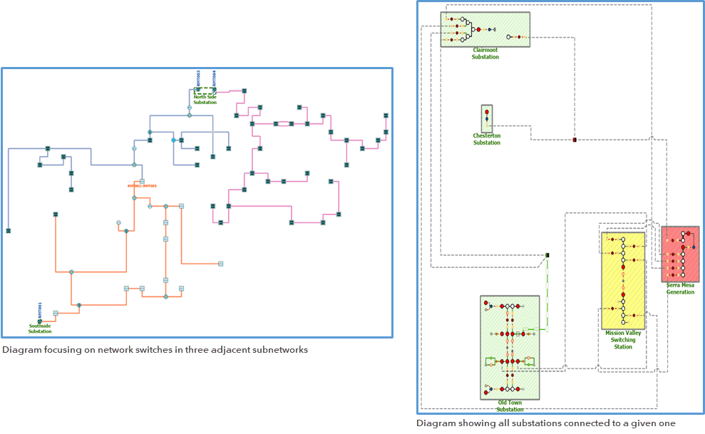
Depending on their settings, diagram templates can be configured for different purposes. For example, to explore the network data and identify potential missing connectivity, to produce clear and synthetic network views focusing on critical devices, to automate diagram generation from preset network traces, and so on.

Once you get familiarized with rule and layout definitions and layer definition for diagram templates, you will quickly take benefits of network diagrams.


Article Discussion: