Real-time kinematic (RTK) drones have been around for years, enabling processing software (such as ArcGIS Drone2Map) to generate output products with centimeter accuracy without the need for ground control points (GCPs), but they have been cost prohibitive for some organizations. As RTK drones are becoming more affordable and the RTK networks they rely on are becoming more accessible, it is becoming increasingly common to own one. However, RTK drones may not always be the turnkey solution for collecting high-accuracy drone products. In this blog, we will discuss how to ensure you are getting the most out of your RTK drone and how to properly set up an ArcGIS Drone2Map project to use imagery collected with an RTK drone.
RTK drones defined
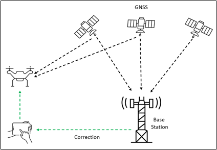
An RTK drone has a high-quality GNSS (Global Navigation Satellite System) module that receives real-time correction from a nearby base station through the drone’s remote control. When the drone is connected to the base station, the base station provides corrected GPS positions to achieve centimeter-level accuracy for the drone in real time, allowing for the creation of highly accurate 2D and 3D products. However, since RTK drones are reliant on constant communication between the drone and the base station, any interference to this connection can degrade the accuracy of the RTK measurements. Some common sources of interference include flying behind obstructions, radio interference, and changes in antenna orientations during flight.

RTK imagery in ArcGIS Drone2Map
Processing images from RTK drones in Drone2Map is just as straightforward as processing imagery from traditional drones. Follow these best practices to ensure you are getting the most out of your RTK drone imagery.
Define the image coordinate system
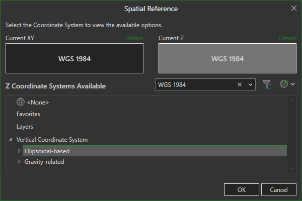
The image coordinate system is the coordinate system that your drone uses to geotag each drone image location. Selecting the correct horizontal and vertical coordinate system for your drone imagery is one of the most important parameters when setting up your Drone2Map project. Most RTK drones record the image locations in the geographic coordinate system WGS 1984 and use the ellipsoid height (also typically WGS 1984) to measure the drone’s altitude. However, it is important to verify the correct image coordinate system with the drone manufacturer and base station before processing your images in Drone2Map.

Define the project coordinate system
The project coordinate system is the coordinate system of your 2D and 3D products after processing is complete. Drone2Map creates output products in the same coordinate system as your imported control. If you have already imported control points, there is no need to set the project coordinate system. If you have not imported control points, use the project coordinate system settings to define the project coordinate system.

Transformations between the image coordinate system and the project coordinate system
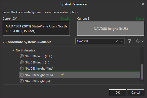
If the image coordinate system and the project coordinate system are based on different geographic datums, a transformation between the two is needed. Drone2Map automatically selects a default transformation when needed. However, more than one transformation may exist, such as when transforming from ellipsoid heights to orthometric heights. For example, when selecting NAVD88 as the project vertical coordinate system, you can select the desired geoid model (Drone2Map 2023.2 and later), such as GEOID12B or GEOID18.

When using RTK drone imagery, accepting the default coordinate systems will typically cause your products to be shifted by 20–30 meters in the vertical direction due to the proper transformation not being applied. If you find that your products are shifted, double-check that the correct coordinate systems and transformation was used.
Image location for high-accuracy GPS
Drone2Map has a processing option that maximizes the capabilities of RTK drones called Fix Image Location for High Accuracy GPS (RTK and PPK). When this option is checked, Drone2Map will not attempt to optimize the location of image positions during the Adjust Images step. This ensures that the images’ locations collected by your RTK drone stay fixed during the adjustment.

Recall from the previous section that RTK drones require a constant connection between the drone and the base station, and that interruptions to this connection can degrade the accuracy of your RTK drone. For this reason, it is important to check the RTK logs and ensure that all drone image locations were recorded with the expected level of accuracy before checking this option. Checking this option in combination with low-accuracy image locations may cause your final products to be inaccurate.
Confirm accuracy
The prospect of being able to create high-accuracy products without the need for collecting GCPs is arguably the most appealing benefit of RTK drones. While it is possible to create high-accuracy 2D and 3D products from an RTK drone without using GCPs, consider that without checkpoints, there is no way to validate the accuracy of your products. Therefore, using checkpoints remains an essential component of the RTK workflow.
Troubleshooting tips
Unfortunately, sometimes things do not go as planned. In this section, we will discuss some troubleshooting tips to help diagnose two common issues when processing RTK drone imagery.
Products are in the correct location, but the accuracy is not as good as expected
- Ensure that accuracy assessments are based on the results of valid checkpoints. If no checkpoints were collected at the time of flight, it may be possible to collect checkpoints after the fact by surveying natural features or landmarks that are visible on the ground and in the drone imagery.
- Review the RTK logs to ensure the image location accuracies are within specification and remove any images that are inaccurate. If image locations are determined to be inaccurate, uncheck Fix Image Location for High Accuracy GPS (RTK and PPK), and you will need to use GCPs to compensate for the poor image accuracies.
- Check overlap and image quality. RTK drones collect high-accuracy image locations. However, poor overlap and bad image quality, such as blurry images, can impact the quality of ground measurements.
Products are shifted in the horizontal or vertical direction
- Check that the correct image coordinate system is used. Verify the image coordinate system with the drone manufacturer and base station.
- Verify the correct transformation between the image coordinate system and project coordinate system was used. For example, a common mistake when selecting NAVD88 as the project vertical coordinate system is not changing the image vertical coordinate system to WGS 1984, resulting in no transformation being applied.
Further resources
- NOAA CORS Network: https://geodesy.noaa.gov/CORS/
- Download the ArcGIS Coordinate Systems Data installation from My Esri
- Drone2Map help: Real-time kinematic processing

Article Discussion: