Creating 3D content for ArcGIS Online
This blog has been updated to show the latest changes we’ve made to help make it easier for you to get your 3D content onto ArcGIS Online with ArcGIS Pro 2.4. I initially wrote this blog back in Sep 2017 showing how you could publish 3D content to ArcGIS Online with ArcGIS Pro 2.0. Since then publishing your web scenes, 3D layers(scene layers and elevation) can now be done in 1 click.
I am going to take the data provided in this ArcGIS Pro tutorial focused on creating 3D content in ArcGIS Enterprise and show you how you can create 3D content for ArcGIS Online. We are going to go over how to create scene layers, elevation layers, style scene layers and feature layers in Scene Viewer and finally create a web app from the web scene we author. *This blog is covering styling layers with Scene Viewer in ArcGIS Online but you could style your layers in Pro and Scene Viewer will support those layer configurations.
What am I using in this blog to create a web app using a web scene with 3D layers?
In this blog I am using:
• Provided data you can download here.
• ArcGIS Pro 2.4
• ArcGIS Online organizational account that supports publishing hosted layers
• Hosted Scene Layers, Hosted Elevation Layers, Hosted Feature Layers
• Scene Viewer
• Web AppBuilder
Creating a Local Scene in ArcGIS Pro
When opening ArcGIS Pro, create a new project and select Local Scene from the Project Templates and give your new project a name.
Remove the default layers from the scene because these layers are cached and are in a different spatial reference from the layers about to be added and lightweight clients like Scene Viewer cannot reproject cached layers. To remove the layers from the scene right click on them and select remove layer. In my default scene I removed the World Topographic and World Elevation layer.
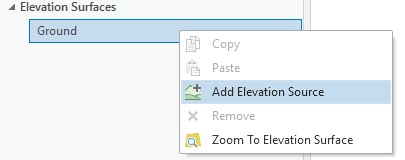
To add the layers provided click on Add Data in the Map tab and select the Portland_Topo raster in the file geodatabase. Next the elevation data needs to be added to the scene. Right click on Ground under Elevation Sources and click Add Elevation Source to add the DTM to the scene.
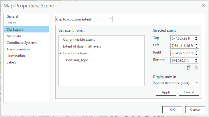
Next add the trees layer to the scene. The trees can stay in the 2D Layer section in the contents pane for now. We will be making changes to them later on in the blog. I want to make sure the extent of the scene is clipped to the base layers of the scene. Right click on Scene in the contents pane and click on Properties. Under the Properties dialog click on Clip Layers and from the drop down select Clip to a custom extent and under Extent of a layer select Portland_Topo.
Creating 3D Buildings – Multipatch Features
The base layers for our scene have been completed so let’s begin working on the operational layers for this web scene. Add the building footprints to the scene in Pro using Add Data on the Map tab. In the table of contents, drag the Buildings layer from the 2D Layers group into the 3D Layers group so we can extrude these buildings and visualize them in 3D. Right-click the Buildings layer and click Properties . On the Elevation tab, click the Features are drop-down menu and click On the Ground.
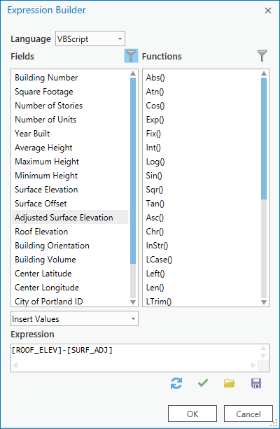
The buildings are now at a height of zero, drawing below the terrain surface. Starting the buildings at a height of zero will ensure the buildings are extruded to the correct height and will not be affected by the slope of the terrain. Click OK to close the Properties dialog box. Click the Buildings layer in the Contents pane and click the Appearance contextual tab. Click Feature extrusion type and click Base Height . Click the Extrusion Expression button . Subtract the Adjusted Surface Elevation from the Roof Elevation, [ROOF_ELEV]-[SURF_ADJ]. Click the Unit drop-down menu and click Feet to match the projection of the data. The buildings are now extruded to the correct height but are not yet aligned with the surface.
After you extrude the building footprints run the Layer 3D to Feature Class tool to create a multipatch feature class from the extruded polygons. For the Grouping Field, click Building ID, and accept all other defaults. Click Run. When you pick the grouping field for the Input features will merge multiple input features into the same output feature. The resulting remaining attributes will be inherited from one of the input records. This will limit the attributes in the output multipatch with only the grouping attribute. I did a join with the polygon layer using building ID to the multipatch dataset and did an export on the multipatch feature class to create a new feature class that will include a set of attributes to use for popups or smart mapping in Scene Viewer.
Publishing a web scene from ArcGIS Pro
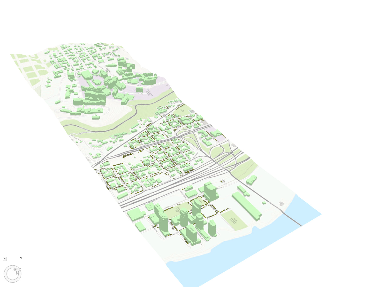
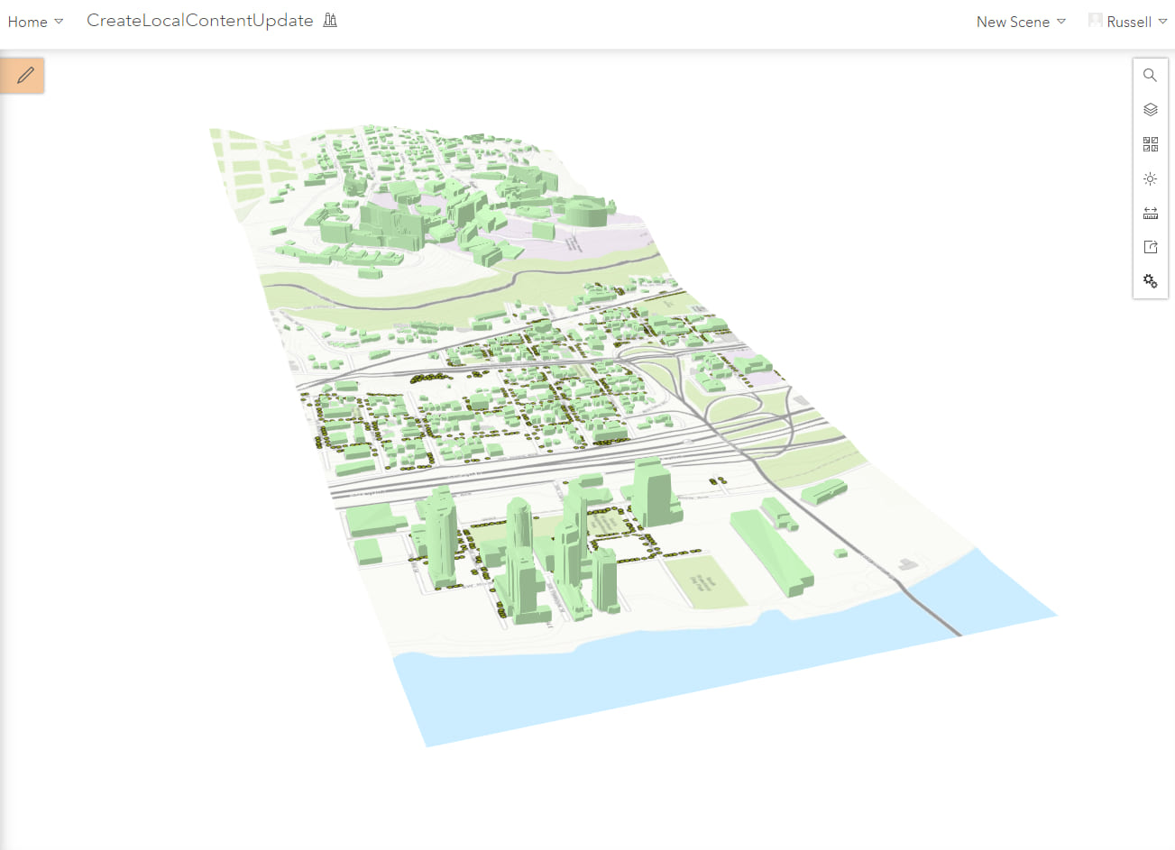
Now that the scene in Pro has a base layer, elevation layer, 2D point layer and a 3D multipatch layer it is ready to be published to ArcGIS Online. Go to the Share tab on and click on Web Scene. This will show you all the layers you are about to publish under the Content section of the Share pane. Under the content section you can configure your layers like editing capabilities or levels of detail for your tile and elevation layers. In this scene there wont be any changes necessary so go ahead and click on Share to begin the publishing process for all of the layers and web scene. The final scene from Pro will look like the image below.
Updating Web Scene in Scene Viewer
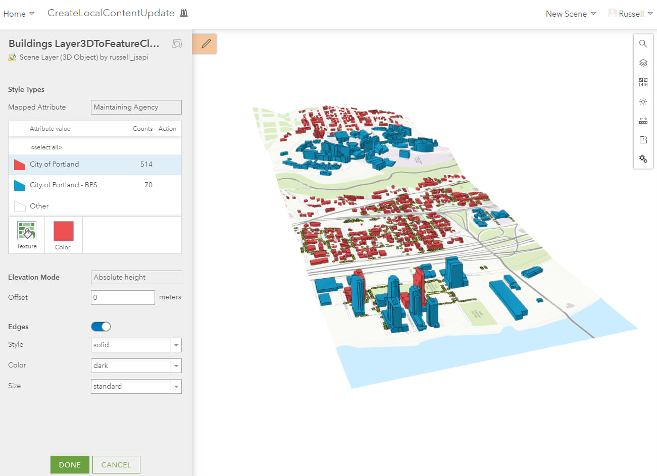
Using the same web scene from Pro we can make changes to it with Scene Viewer. First we will change the colors of the buildings by clicking on the layer in the contents pane. For this layer I am using the attribute Maintaining Agency to style the buildings scene layer using the Types smart mapping renderer which will uniquely color the buildings based on that attribute value. Going into the options for the Types style you can change the colors used and enable edges which can add more detail to your buildings. You can also set to hide the legend or disable popups.
Using Web Styles to Style Points
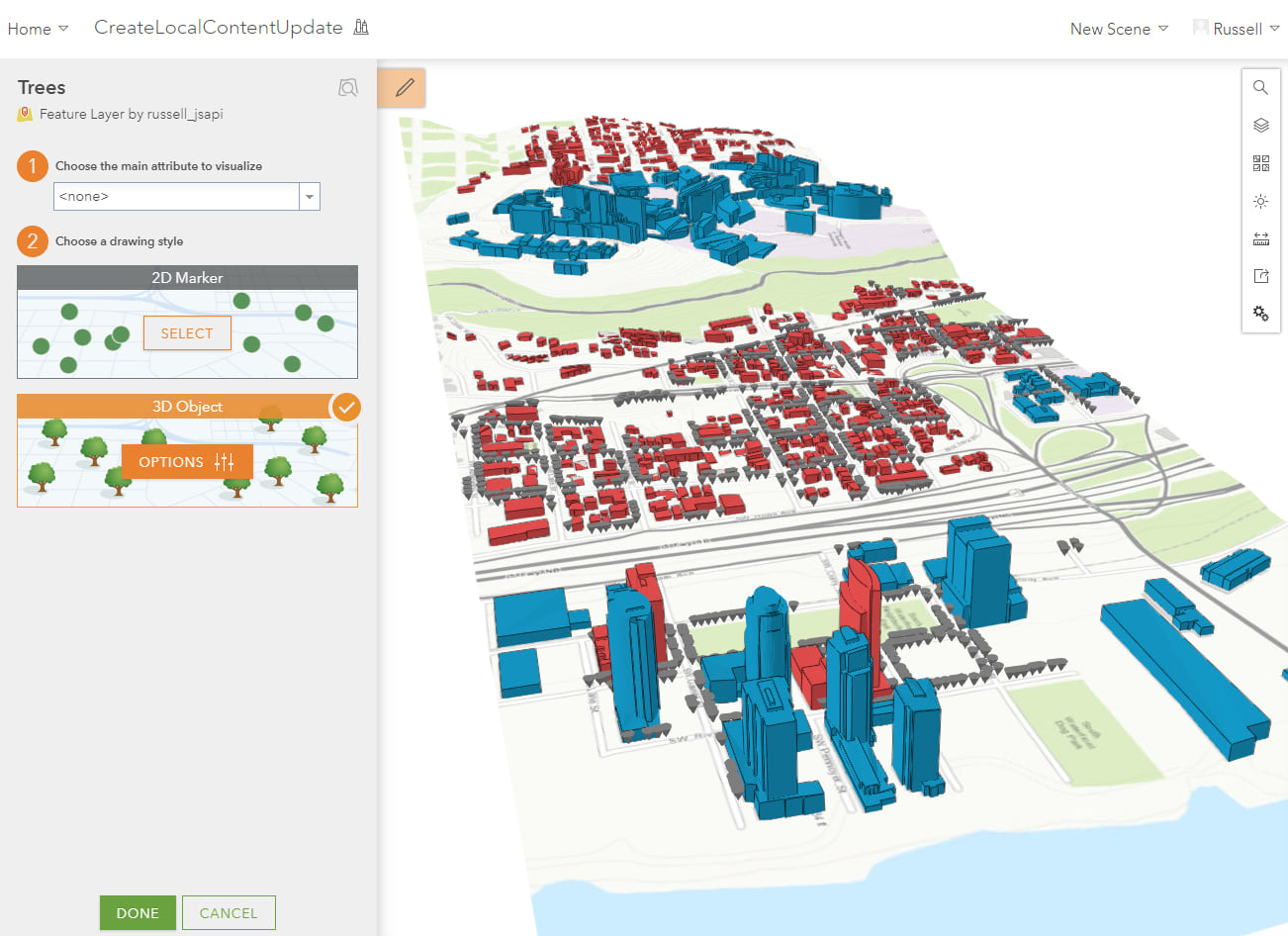
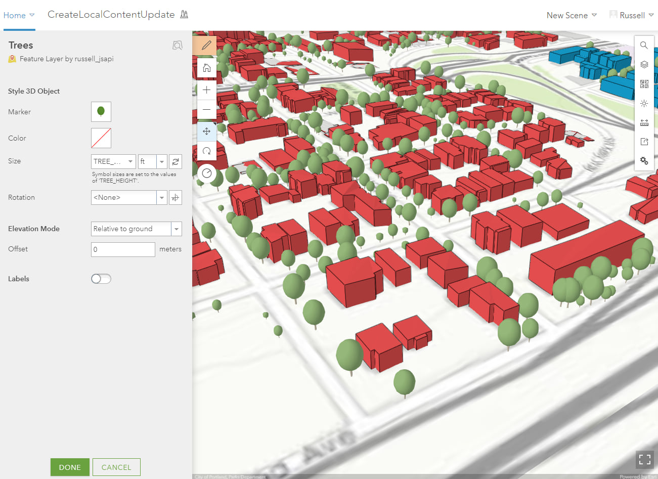
The next thing we want to do is style our trees layer as trees! Click on the trees layer to open the designer pane and you will see the option to display the trees using 2D or 3D styles. You can also use attributes in the drop down menu to bring up 2D and 3D options for Counts and Amounts or Types(Unique Renderer) smart mapping styles. Click on 3D Object and click options.
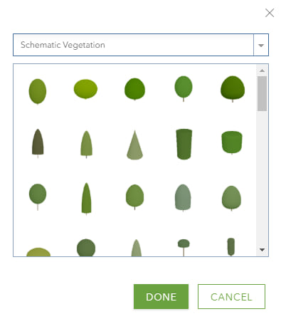
On this panel we can choose from the Esri provided web styles and configure similar options like show popups, legend and offset. Click on the Symbol and select Schematic Vegetation and pick a tree you want to style the layer with.
Next we want to use the attribute TREE_HEIGHT to drive the height of the trees in the scene. The tree height is recorded in ft so choose that unit of measurement on the drop down menu next to the attribute you selected.

Here is what the web scene will look like after the tree layer has been fully configured using the height attribute.
Using Slides and Daylight
The layers in the web scene are now fully configured we can go ahead and create slides and configure the daylight settings which is also stored in the slides. To change the Daylight click on the sun symbol on the right hand side of Scene Viewer and move the slider to change the suns position. This will move the suns location and with that you will see the shadows for the buildings and trees move.
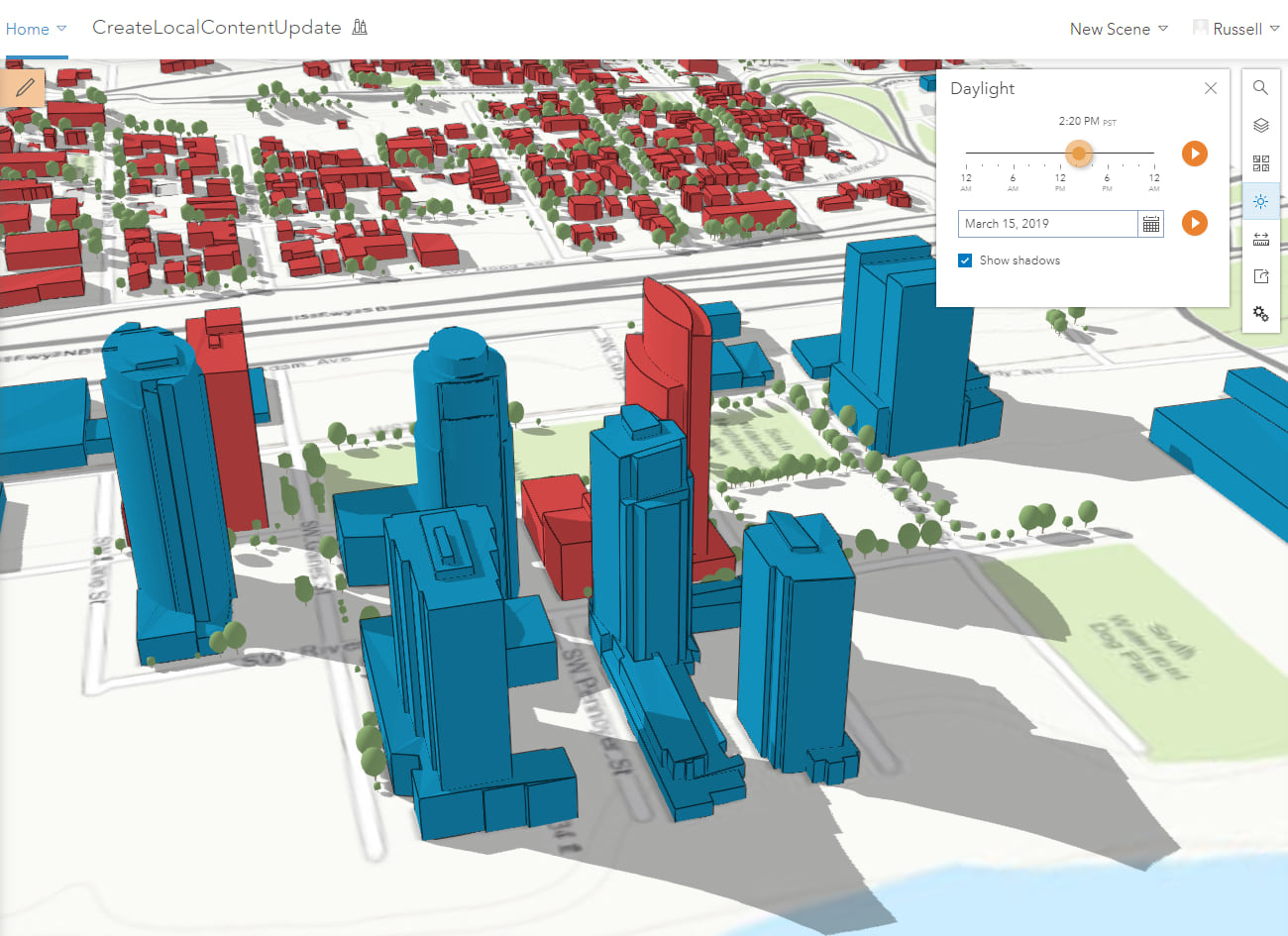
Now open up the Slides option and click on Create Slide to capture this configuration of the web scene in the slide. You can pick different locations and different times of day as you create more slides. Once you have created the slides you want click Save to apply these changes to the web scene.
With the web scene ready you can create a configurable web app in just a couple clicks. To learn how to create a a web app from Scene Viewer check out this blog I posted here.

Commenting is not enabled for this article.