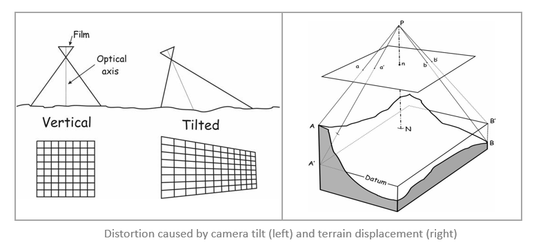
Any remote sensing image, whether it’s a drone image, aerial photograph, or data from a satellite sensor, will inherently be impacted by some form of geometric distortion. The shape of local terrain, the sensor angle and altitude, the motion of the sensor system, and the curvature of the Earth all make it difficult to represent three dimensional ground features accurately in a two dimensional map. Image orthorectification corrects for these types of distortion so you can have a measurable, map-accurate image.

Everyone working with GIS data to make well-informed decisions needs up-to-date information about the natural, man-made, and cultural features on the ground: roads, land cover types, buildings, water bodies, and other features that fill the landscape. Much of the vector data that describes these features was actually created from orthorectified imagery, and can be combined with new imagery to update your landbase.

Esri’s Ortho Mapping suite enables you to orthorectify your remote sensing imagery to make it map-accurate. It also makes it easy to create other products like orthomosaics (mosaicked images corrected for distortion) and digital elevation models (terrain or surface models) which can be used as basemaps, part of a landbase, or for further analysis in stereo models, 3D analysis and feature extraction.
The workflow to create ortho mapping products will be presented in a three-part blog series:
- Creating a workspace
- Performing a block adjustment
- Creating ortho mapping products
Let’s get started!
Creating an Ortho Mapping Workspace
The first step in any project is getting organized – and creating an Ortho Mapping Workspace in ArcGIS Pro makes this easy to do.
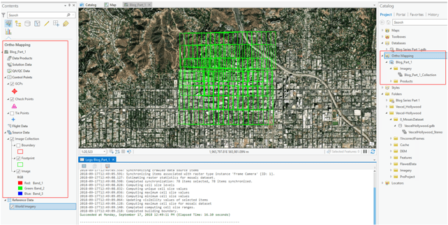
The Ortho Mapping Workspace is a sub-project in ArcGIS Pro; it’s the interface you work with when interacting with ortho mapping workflows. The workspace is defined by the type of imagery you are working with (drone, aerial or satellite). In turn, the workspace is integrated with the tools and wizards to properly guide you through each step in the workflow. When you create a new workspace, an Ortho Mapping folder appears in your project folder structure in Catalog, and a new table of contents list view allows you to List By Ortho Mapping Entities. Again, the types of feature classes and tables you see in the Contents pane depend on the type of imagery you are working with.
Similar to Maps or Scenes within a project, a workspace is an object stored in the folder structure of a project and it can be accessed by other projects. All the feature classes and tables needed to orthorectify your imagery are created and managed in the workspace.
5 Simple Steps
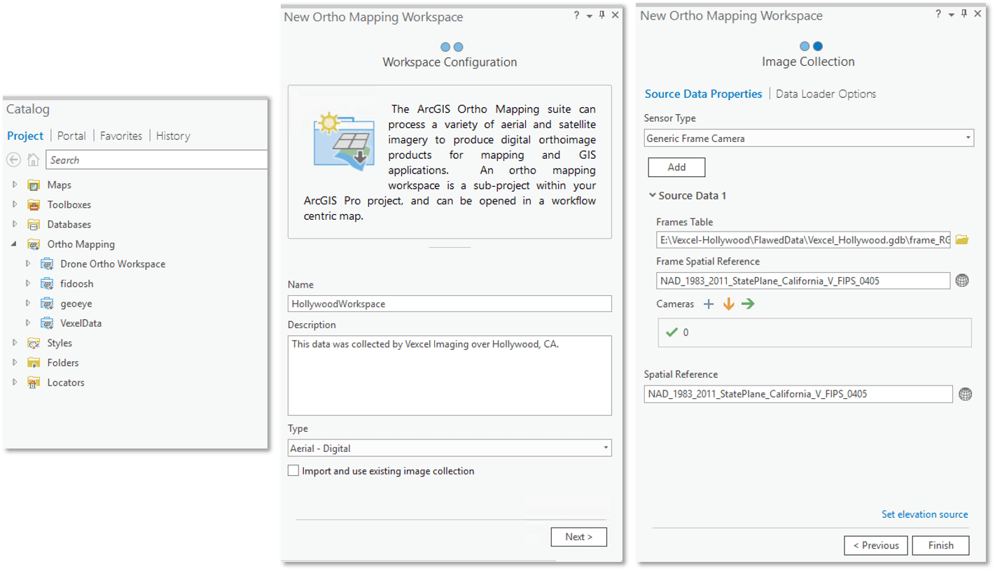
Step 1: Open the Imagery tab in your ArcGIS Pro project. This is where you can analyze and manage any raster data you want to work with in Pro. In the Ortho Mapping group, you’ll see the New Workspace menu that allows you to create a New Ortho Mapping Workspace, add an existing Ortho Mapping Workspace with a reference to that workspace, or import an Ortho Mapping Workspace by creating a copy of an existing workspace and storing the new copy in your project. Select New Workspace.
Step 2: The New Ortho Mapping Workspace wizard appears. Here you’ll give your workspace a name (required) which identifies your project in the Contents and Catalog panes. You can also provide a description (optional) and you’ll select the type of imagery you want to import. In our workflow, we’re using aerial imagery acquired by Vexcel Imaging covering an area over Hollywood, California, so we’ll select Aerial – Digital as the type. Click Next.
Step 3: The Image Collection page opens. Here you’ll enter specific information about cameras and exterior orientation to enable correction of sensor-related distortion. Under Sensor Type, you can choose from MATCH-AT, ISAT, or Applanix project files, or you can select the Generic Frame Camera if you have a table of orientation data output from an aerial triangulation or direct georeferencing application. To edit the Camera parameters, you can hover over the Camera ID and click the Edit Properties button. You’ll then provide the exterior and interior orientation information with the Frames table and Cameras table, respectively.
The Frames table has a specific schema that is required in the ortho mapping workspace for aerial imagery. It contains the exterior orientation and other information specific for each image comprising your image collection. The Cameras table contains all the camera calibration information for computing the interior orientation, but you can add the camera information manually in the wizard or as a table. To edit the Camera parameters, you can hover over the Camera ID and click the Edit Properties button.You’ll also need to specify the Frame Spatial Reference, which be provided with your data.
In our workflow, we used the exterior orientation information that was provided along with our source imagery to create the Frames table in the necessary schema. We then point to a table that has the information for one camera, with CameraID = 0 (see the screen shot below – there’s a check mark next to the 0 under Cameras).
*We are updating this for ArcGIS Pro 2.3 to be more user-friendly for a better experience 🙂

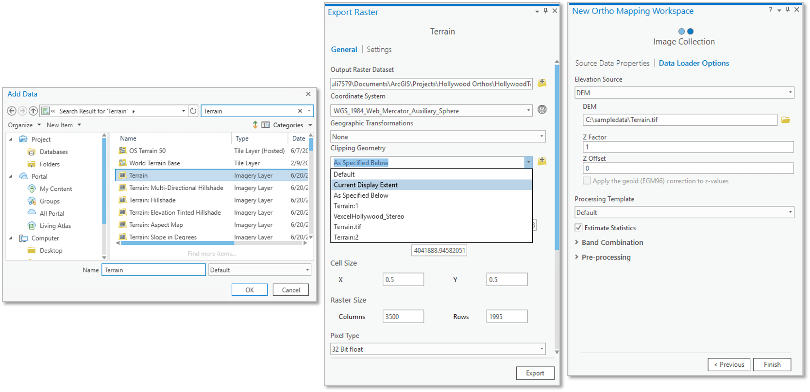
Step 4: To correct for terrain displacement, you need to include an elevation source. The cool thing about working with the ArcGIS platform is you can access the thousands of maps, apps and data layers available in the ArcGIS Living Atlas, so if you don’t have your own elevation data you can search for one and use it into your project. Here’s what we did:
- In our ArcGIS Pro project, zoom to the area of interest in Hollywood.
- On the Map tab, click Add Data and Add data to the map.
- Select the Living Atlas option under the Portal group and search for “terrain” and add the Terrain Imagery Layer.
At first, you might not be able to see much variation in the terrain. Click on the Appearance tab under the Image Service Layer group and select DRA (Dynamic Range Adjustment) to stretch the terrain imagery in the extent you are viewing. - In the Contents pane, right-click on the Terrain imagery layer and select Data > Export Raster.
- In the Export Raster settings, specify the output raster dataset and set the Clipping Geometry to Current Display Extent.
- Click Export.
Now we can add our new DEM to the workspace. To do this, open the Data Loader Options pane in the Image Collection page. Click the browse button to navigate to the DEM created above, or use your own DEM.

Step 5: Finally, we left all the other values as default and clicked Finish.
A Log window will tell you how the creation of the workspace is coming along, and if there are any problems, an error message will be displayed. When it’s complete, you’ll see the new Ortho Mapping Entities in your Contents pane: various control points including Ground Control Points, Check Points and Tie Points, the mosaic dataset that was created using your source data, and placeholders for Data Products, Solution Data, and QA/QC Data that haven’t been created yet.

Make sure to zoom and pan around the map to check out your Image Collection. With the Image Collection selected in the Contents pane, you can open the Data tab from the Mosaic Layer context menu. Here you can change the Sort and Overlap options for your mosaic dataset. We recommend using the Closest to Center or Closest to Nadir options for viewing.
Now that you have all your ortho mapping components organized in your workspace, the next step is to block adjust your data to make sure it’s map-accurate. Stay tuned for the next part of this blog series, Ortho Mapping with Aerial Data Part II: Getting Adjusted, where we’ll show you how to perform a block adjustment to make sure your data is ready for product generation and stereo compilation!
We showed you how to set up an ortho mapping workspace for aerial imagery. For an example of how to set up an ortho mapping workspace for satellite data, check out this short video!


Commenting is not enabled for this article.