Introduction
Update: ArcGIS Pro 3.5 added new tools to bulk apply error resolutions to topology errors. The concepts outlined in this series of articles are important to understand when choosing which actions to use when resolving your errors. Learn more about how to use these new tools by reading the Analyzing topology errors and Resolving topology errors articles.
The first time you run the validate topology tool on your utility network and encounter a topology error you will likely ask yourself three questions:
- What caused this error?
- How can I fix this error?
- What can I do to prevent this from happening again?
The purpose of this article is to provide water industry-specific examples of the most common errors, so you are better equipped to answer these three questions. The different resolutions aren’t always immediately obvious, and we hope this guide will help you quickly identify the solution that’s the best choice for your data and your specific situation.
If you’re not already familiar with error management in the utility network, you will want to familiarize yourself with the following resources:
- You can find a full list of all the possible network errors on the Errors topic in the online help.
- Read the Feature restrictions and rules topic to learn the difference between a network rule and a feature restriction, along with the constraints for what types of features can be connected or associated.
- Read the Dirty area management with the utility network article to learn how the utility network uses dirty areas to track and validate edits made to the network topology.
- Read the Managing Topology Errors article for a higher-level overview of error management.
You can find more water content in the reading lists for Water Utilities, Stormwater, and Wastewater, as well as these hands-on tutorials related to this article:
- Fix Connectivity Errors in a Utility Network
- Fix Topology Errors in a Utility Network
- Configure rules for a Utility Network
You can use the following links to quickly navigate to the different errors:
| Error Type | Error Description |
| Junction-Edge Errors | 8: Invalid connectivity – No junction edge rule |
| Ambiguous Connectivity | 9: Invalid connectivity – More than one junction edge rule applicable |
| Edge-Edge Errors | 10: Invalid connectivity – The edges are different subtypes and cannot connect |
| Stacked Points | 25: Stacked point features |
| Invalid Terminal Connections | 36: The line feature has an invalid terminal |
| Midspan Terminal Devices | 38: Devices with multiple terminals cannot be midspan |
Junction-Edge Errors
Fix Incorrect data
If you incorrectly classify service valves as system valves you will get an error.
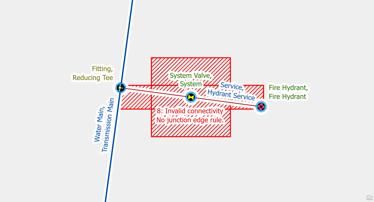
This is because the rules of the water model do not allow system valves to connect to service lines.
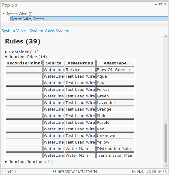
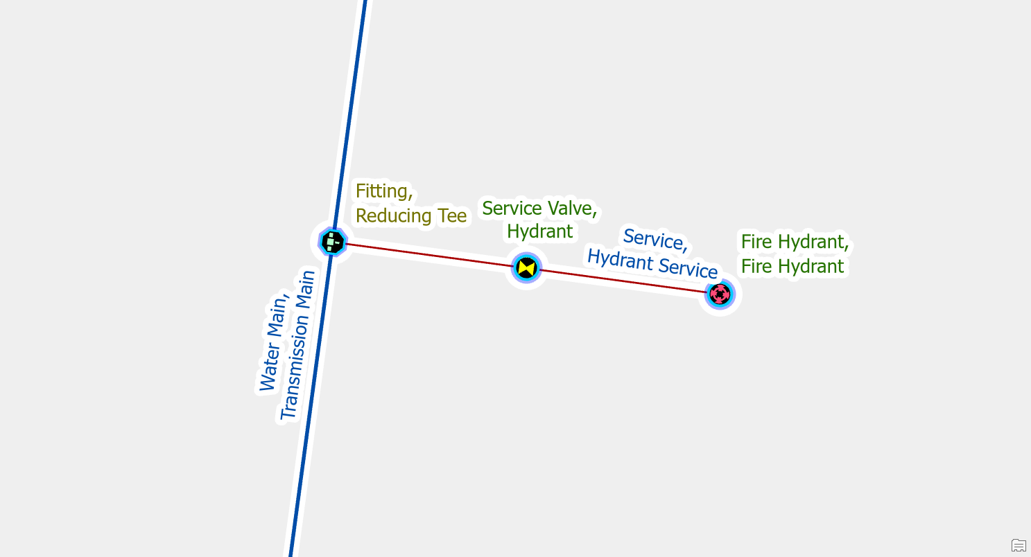
To fix the error you set the asset group and asset type of the service valve to the correct type of service valve for the service line (hydrant, service, etc.).
Add a rule
You must add rules to your network any time you add a new asset type, like a new type of fitting, to your model.
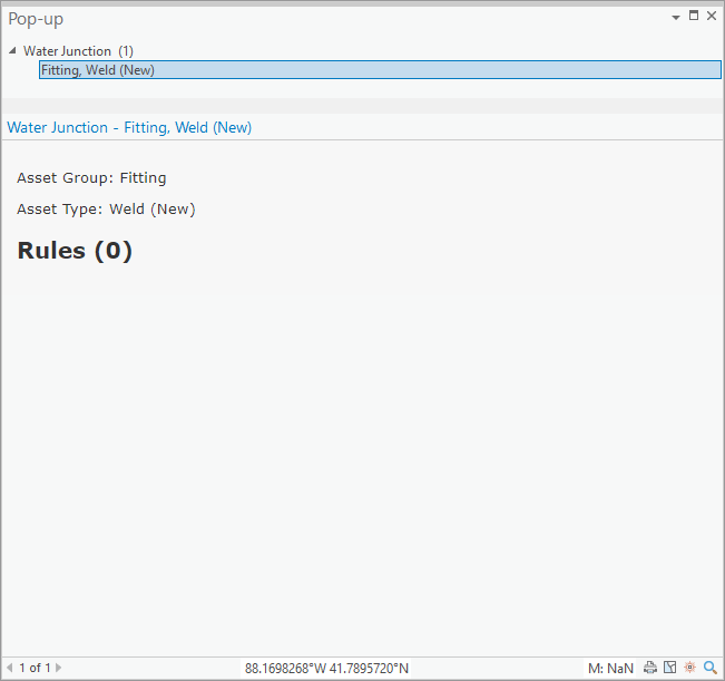
If you place one of these features that doesn’t have any rules that allow for connectivity you will receive errors on it and will be unable to update the corresponding subnetwork.
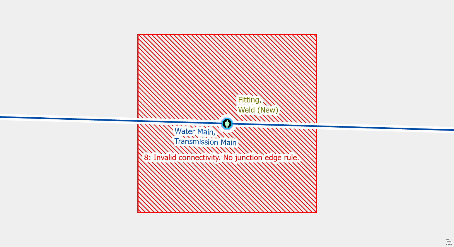
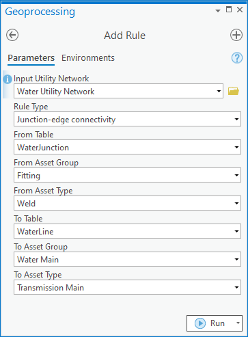
To fix the error an administrator would need to add the rule(s) required for the new type of feature to allow it to connect to different lines, junctions, devices.
They will also need to add the new asset type to the subnetwork definitions for the system and pressure tiers.
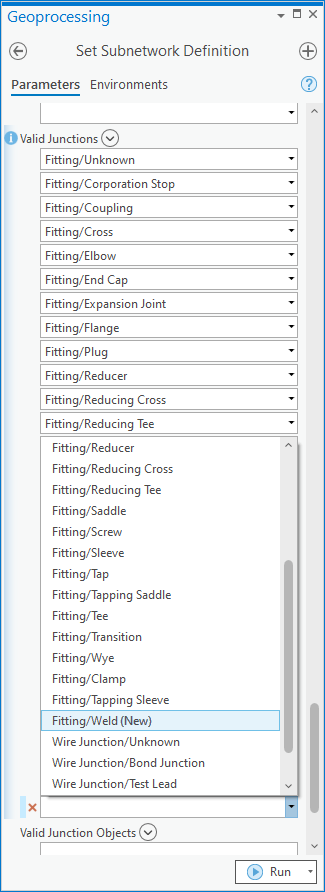
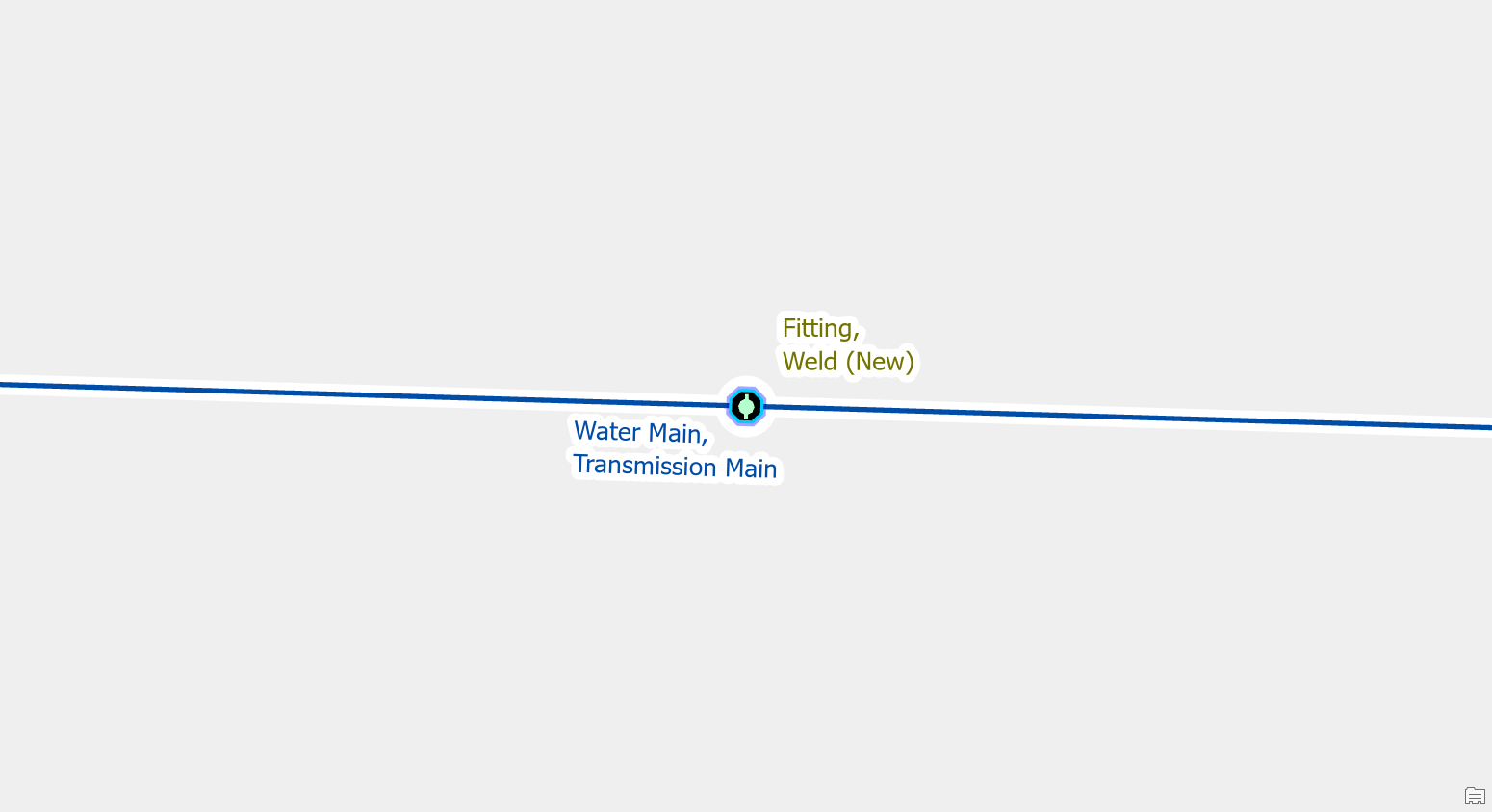
Once the rules and subnetwork definition have been updated you can then validate the area to ensure the error is resolved.
Ambiguous Connectivity
Use Terminal Connections tool
For example, if you forgot to assign the terminal connections on the lines after creating a pump you will run into this error.
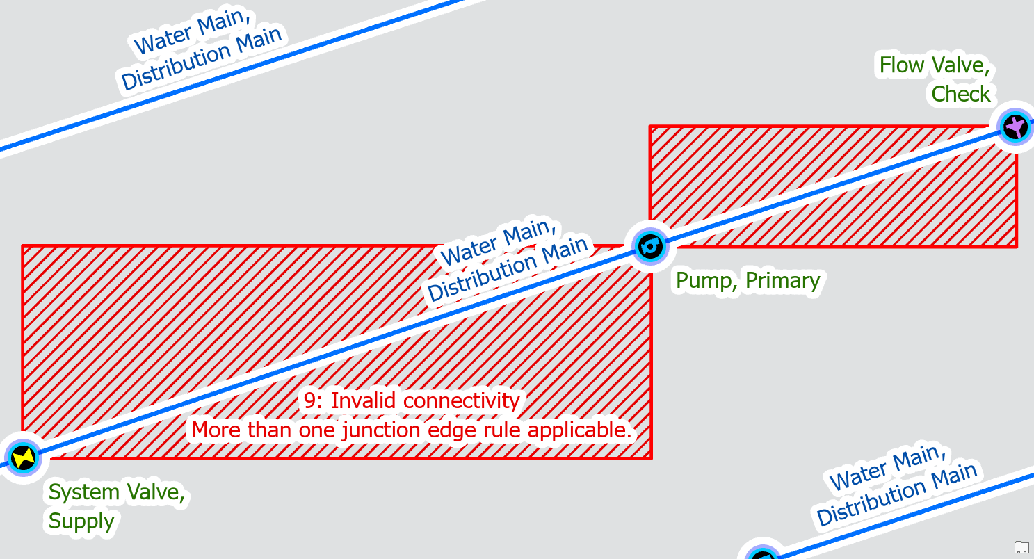
To correct the error, you can use the assign terminals tool on each line that connects to the pump to assign the line to the inlet / outlet of the pump. For other types of features, the naming convention of the terminals may be different but the process for assigning terminal connections is the same.
Once you’ve made and validated the edits, the errors will disappear.
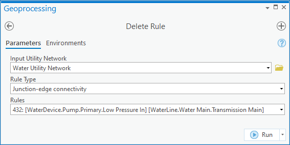
Remove the invalid rule
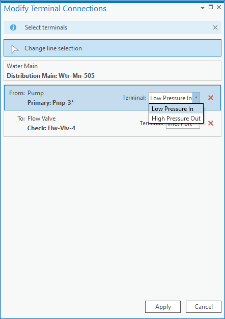
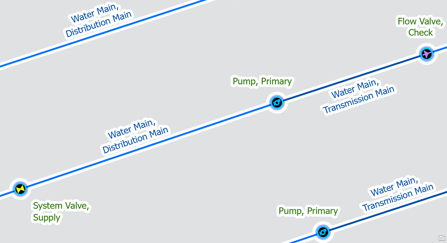
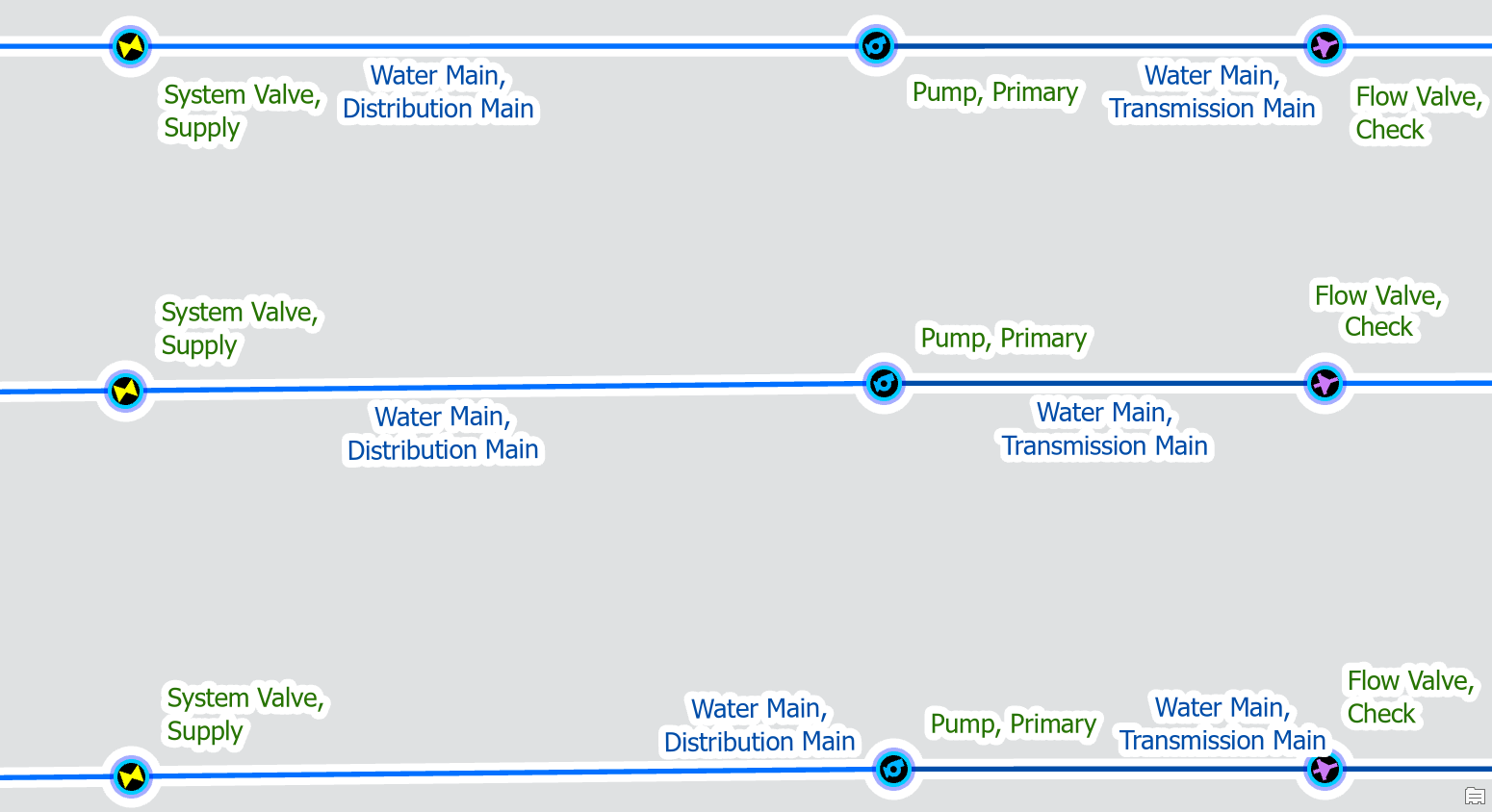
By default, the water model allows transmission main and distribution main to be on both the high-pressure outlet and low-pressure inlet of a pump. This means you must use the terminal connection tool when connecting a main to a pump station to assign it to the right terminal.
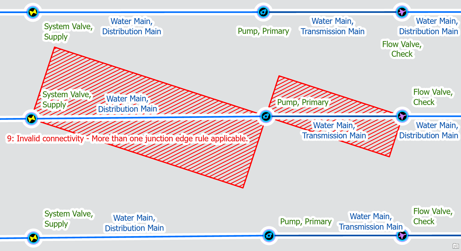
If your data only allows for transmission to be on the high-pressure outlet terminal, then you can remove the rule that allows transmission to connect to the low-pressure inlet. We will keep both rules for distribution mains, since pumps in pumping stations can have distribution on both the low-pressure and high-pressure ports.
This will ensure that transmission mains are always connected to the high-pressure outlet, automatically connect them to the correct side of the pump. Because distribution mains can be connected to either terminal, you must still use the Modify Terminal Connections pane to specify that in this instance, this distribution main is connected to the low-pressure inlet.
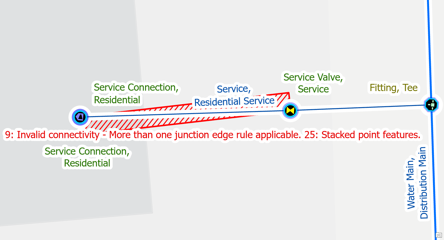
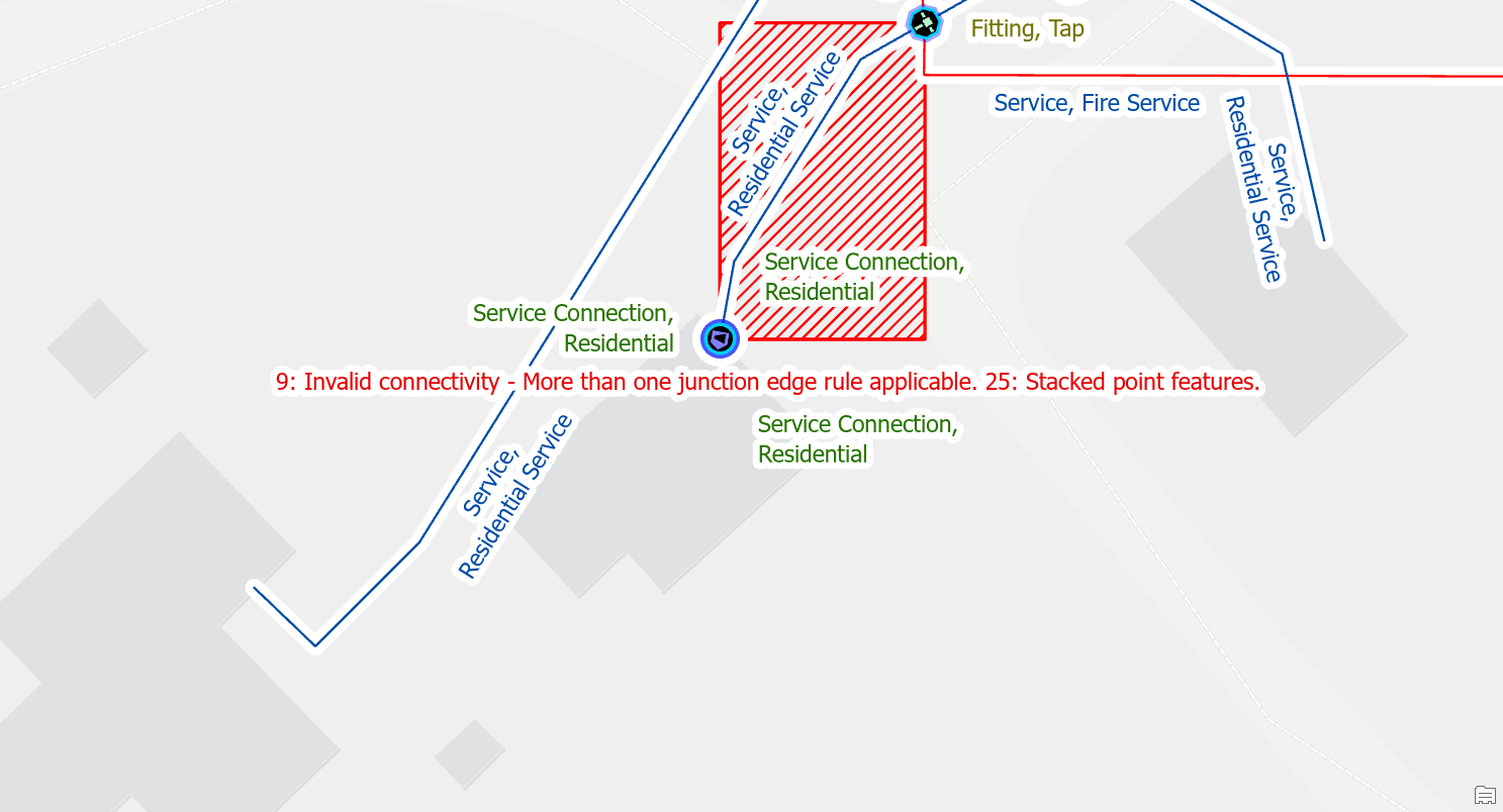
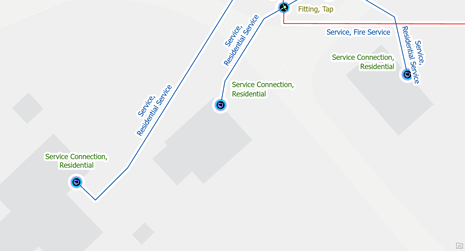
Move one of the features
If you have a service valve drawn on top of a service tee, tap, or other fitting you will want to offset the service blow off valve by moving it away from the saddle, along the service line. This will often result in many different errors appearing at the same time:
- Ambiguous connectivity error because the junctions and lines each have multiple rules
- Stacked point feature errors for the junction and device.
- Edge-Edge errors for the underlying lines because none of the junctions or devices at the area have connected the edges
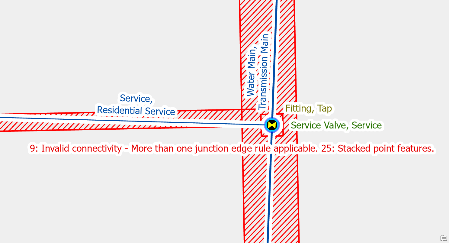
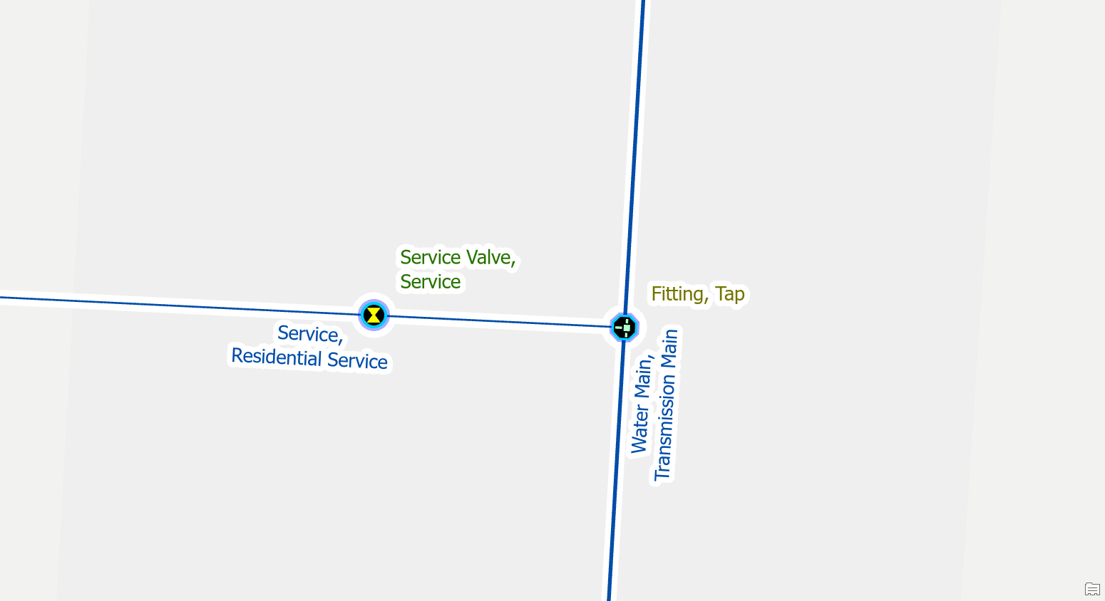
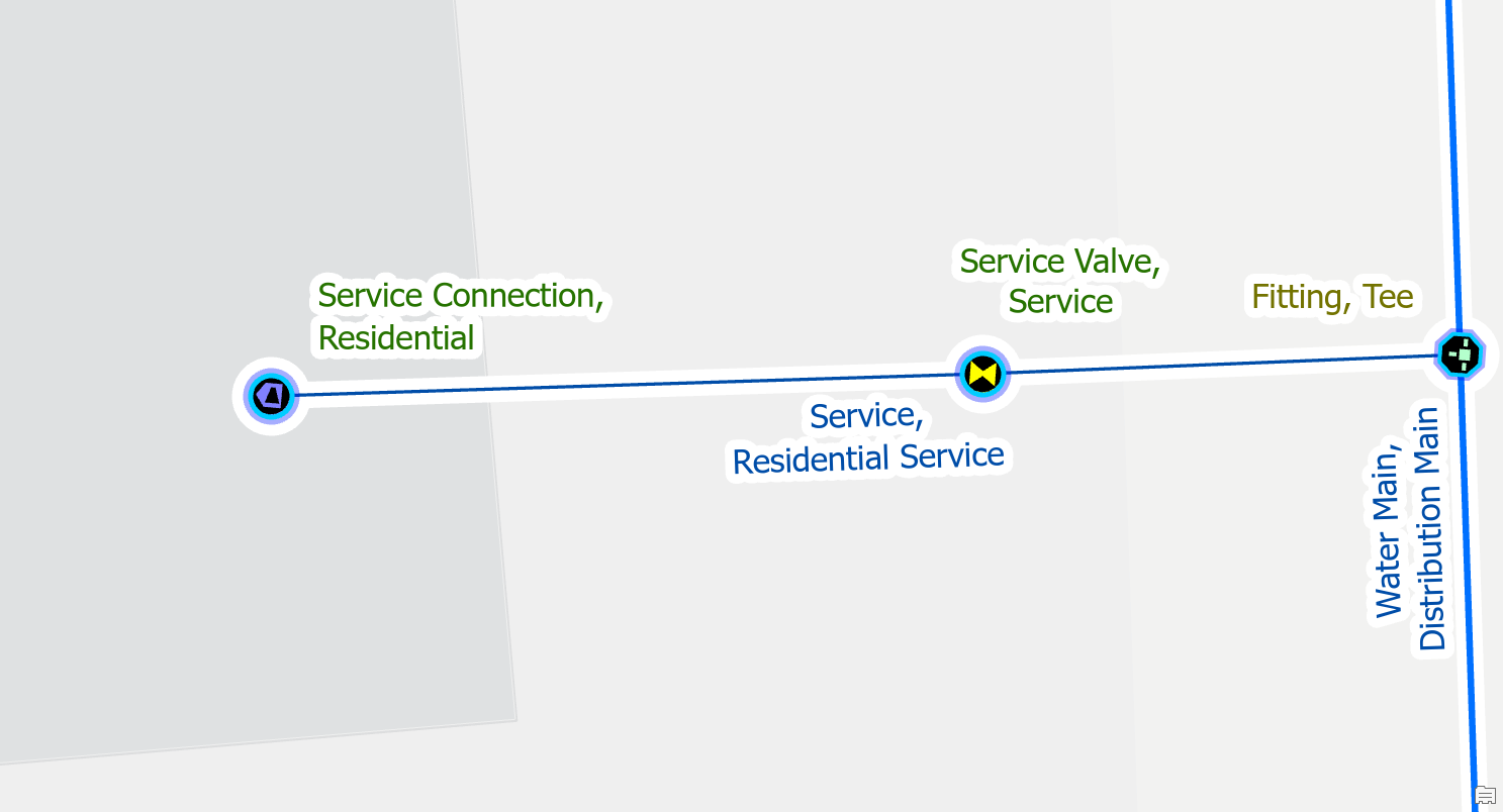
To fix the error, you offset the junction and device.
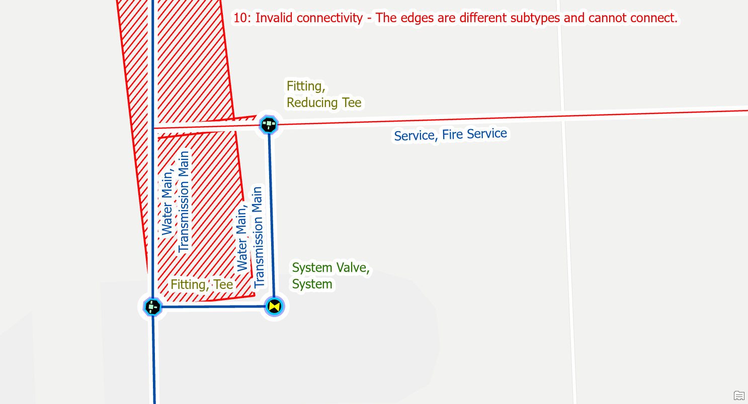
Edge-Edge Errors
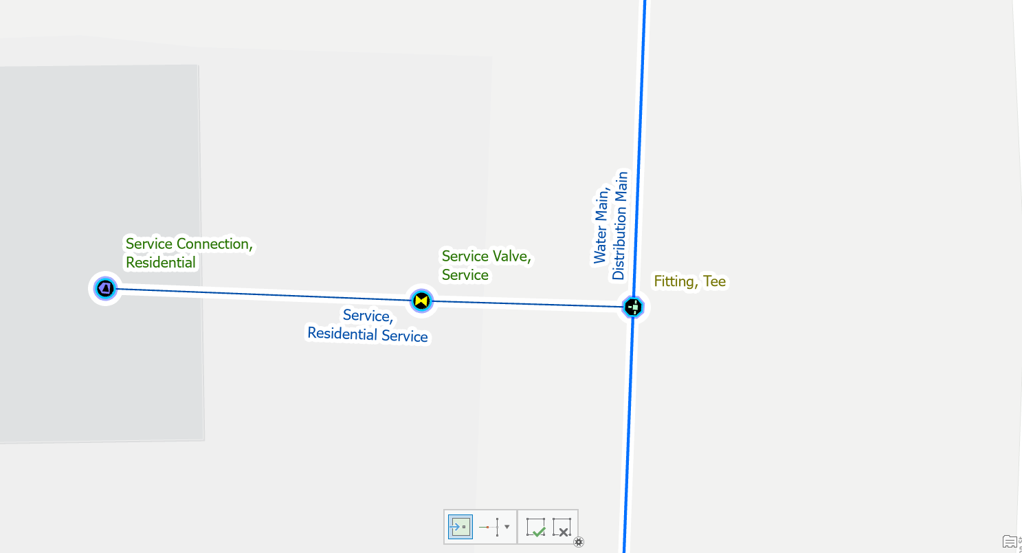
Create a point feature between the two lines
The most common example of a missing junction error is when a service is connected directly to a main without any kind of fitting.
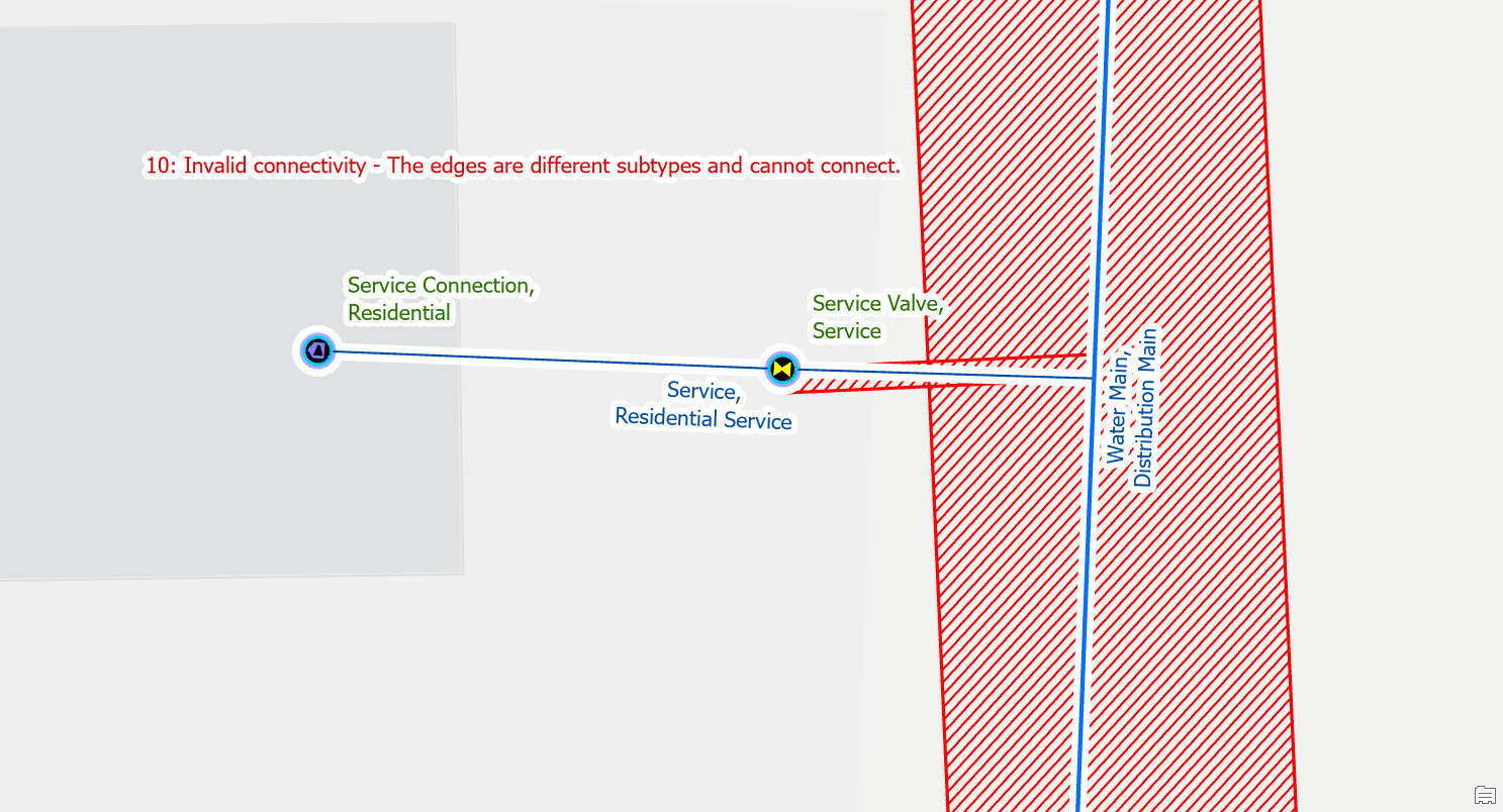
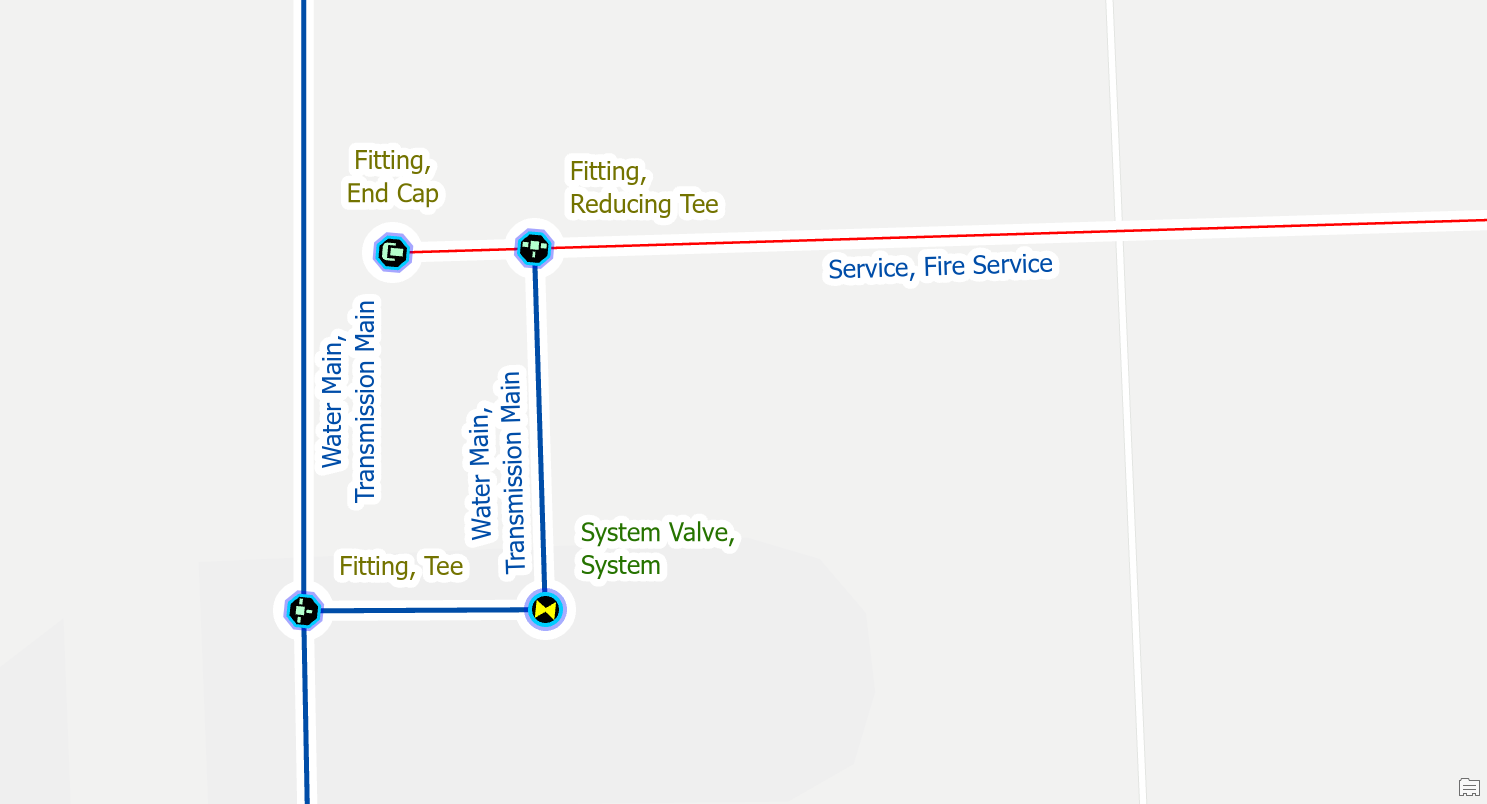
To fix the issue, you would place a fitting at the location where the two pipes are connected. You should make a note or indicator to keep track of these junctions for follow-up. Their location and materials are approximate and will need to be confirmed by referring to source drawings, work orders, or field verification.
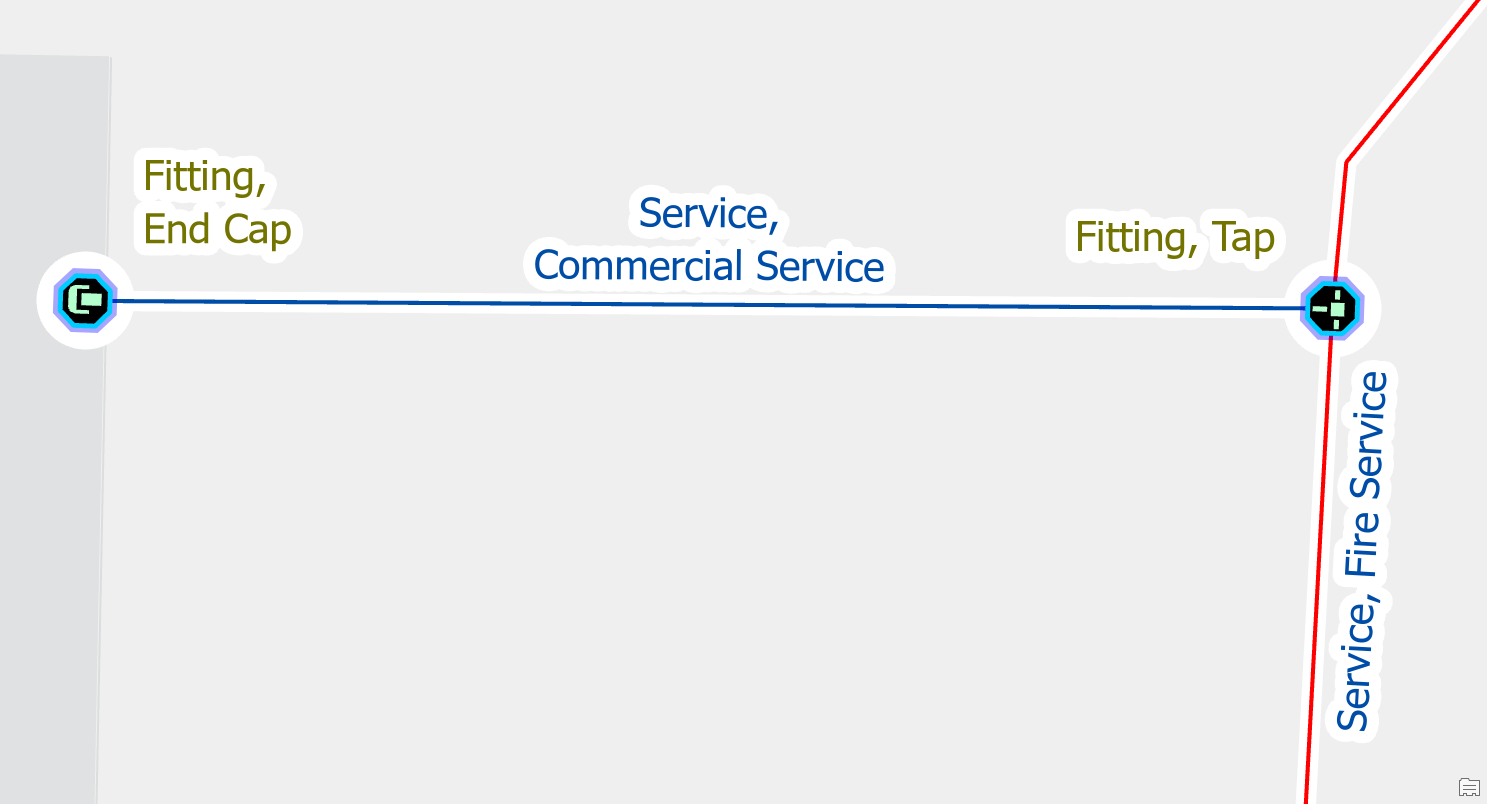
Edit the line features to match
When importing service information from external systems, you may end up with inconsistent asset types in your data. When you connect inconsistent services you will get an edge-edge error.
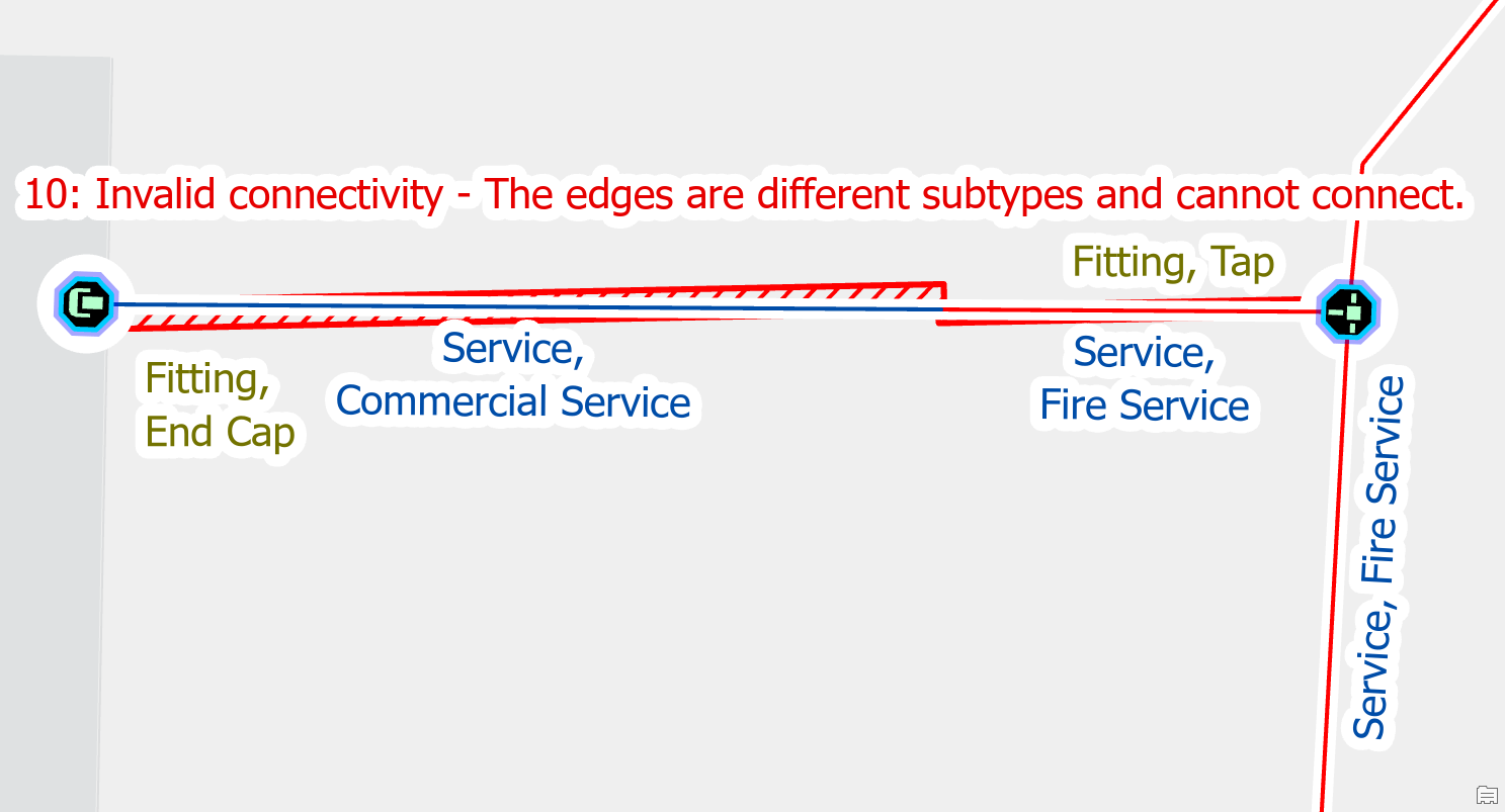
If you look at the two connected services and find that they are the same asset type you can correct the error by updating the asset type on improperly classified pipe or by merging the two lines into a single line.
Move a line
The Utility Network prevents you from snapping different pipes together in a way that causes this error. This error most often occurs when a user accidentally splits overlapping lines or changes the classification of existing lines.
To fix the issue you would perform the following:
- Select the pipe that needs to be unsnapped
- Activate the edit vertices tool
- Move the vertex of the first line away from the second
This will cause the error to go away, but if this results in the feature becoming isolated from your network you will need to research how it is connected.
Stacked Points
Delete one of the stacked features
When you import customer meter locations into the GIS for the first time, it is common for meters to be stacked on top of each other. Each stacked meter will result in a stacked point error.
If you can find that one of the stacked meters is a duplicate, then you should remove the duplicate meter.
Move one of the features
Let’s consider another situation during data cleanup data after importing customer meter locations. In this situation, we are cleaning up data at an address that has multiple meters.
In this situation you would unstack the meters and connect each one to its own service line. If your data does not have enough service lines, or if it is unclear which meter is associated with each service line, then you may need to perform a field check to find the true location of each meter.
Invalid Terminal Connections
Reset terminal connection
If you delete, move, or reclassify a device with terminals, the line it was connected to will still have attributes that reference the terminal from the previous device. This often occurs when working with equipment near stations, supplies or isolation valves.
To fix this error, you use the Modify Terminal Connections pane to remove the invalid connection then validate the edit.
Connect new terminal
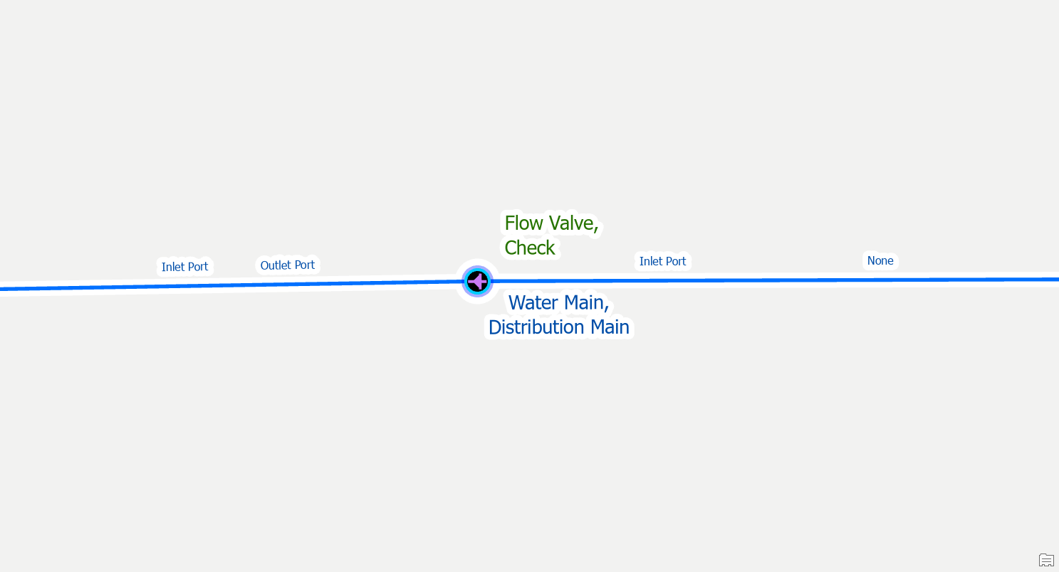
If you replace a device with terminals with a device that has a different terminal configuration you will also receive these errors. In this example we originally placed an air gap flow valve on the line, assigned terminal connections, then later realized it was a check valve. After correcting the valve type, we now receive an invalid terminal error because check valves use a different terminal configuration.
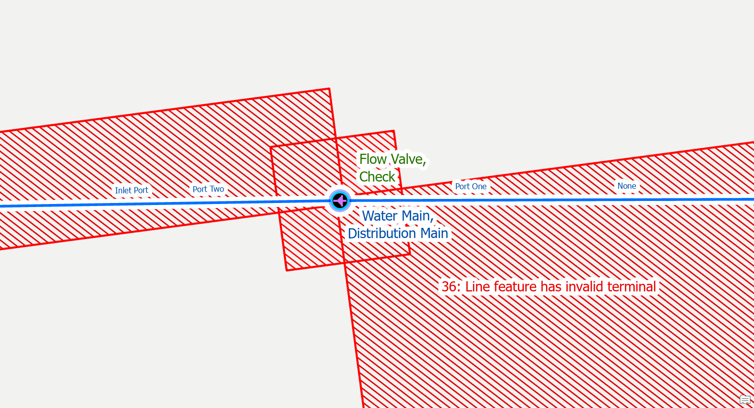
Using the Modify Terminal Connections pane you can assign the new terminal. The pane will only present you with terminals that are valid for the current device.
Midspan Terminal Device
Split the Line
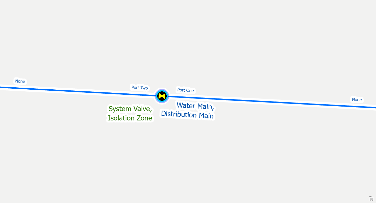
If you place a device with terminals on a line without splitting it first, you will receive this error. You are likely to receive this error when placing new check valves or system isolation valves.
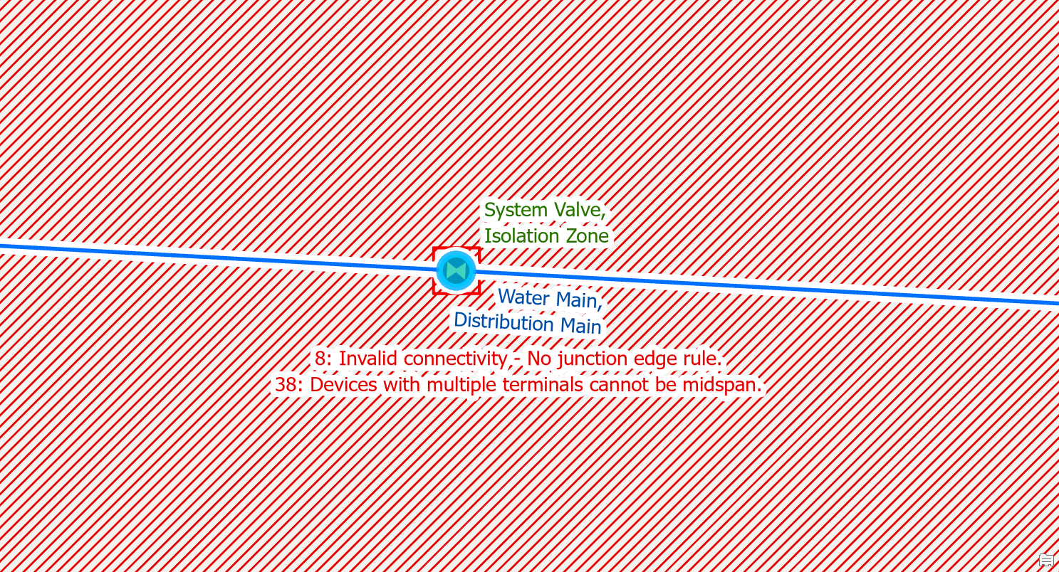
To fix the issue you use the edit tool to split the line at the location where the device connects to the line. After you’ve split the line you will still need to use the modify terminal connections tool to connect the lines to the correct terminals on the device.
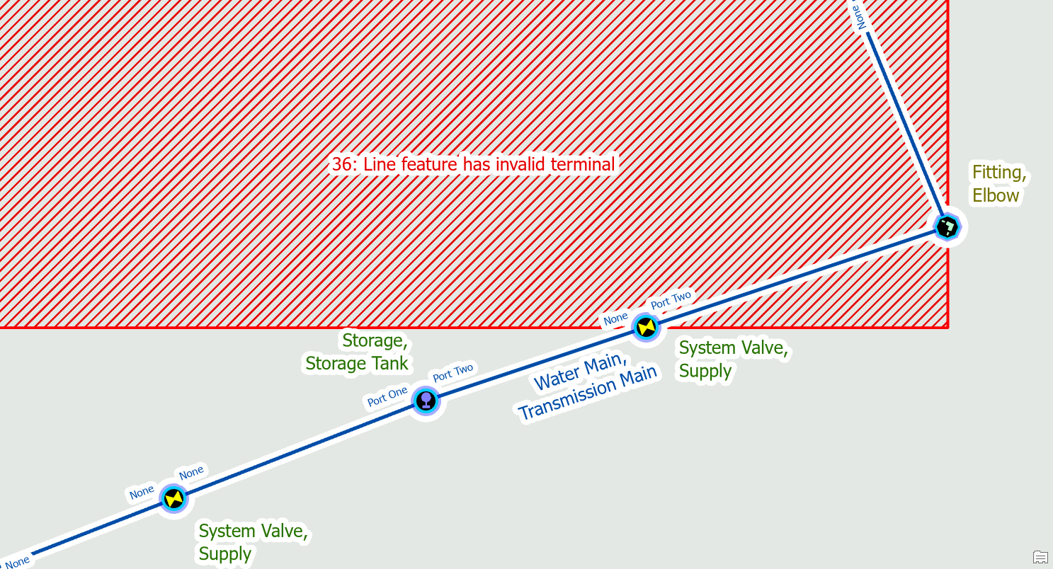
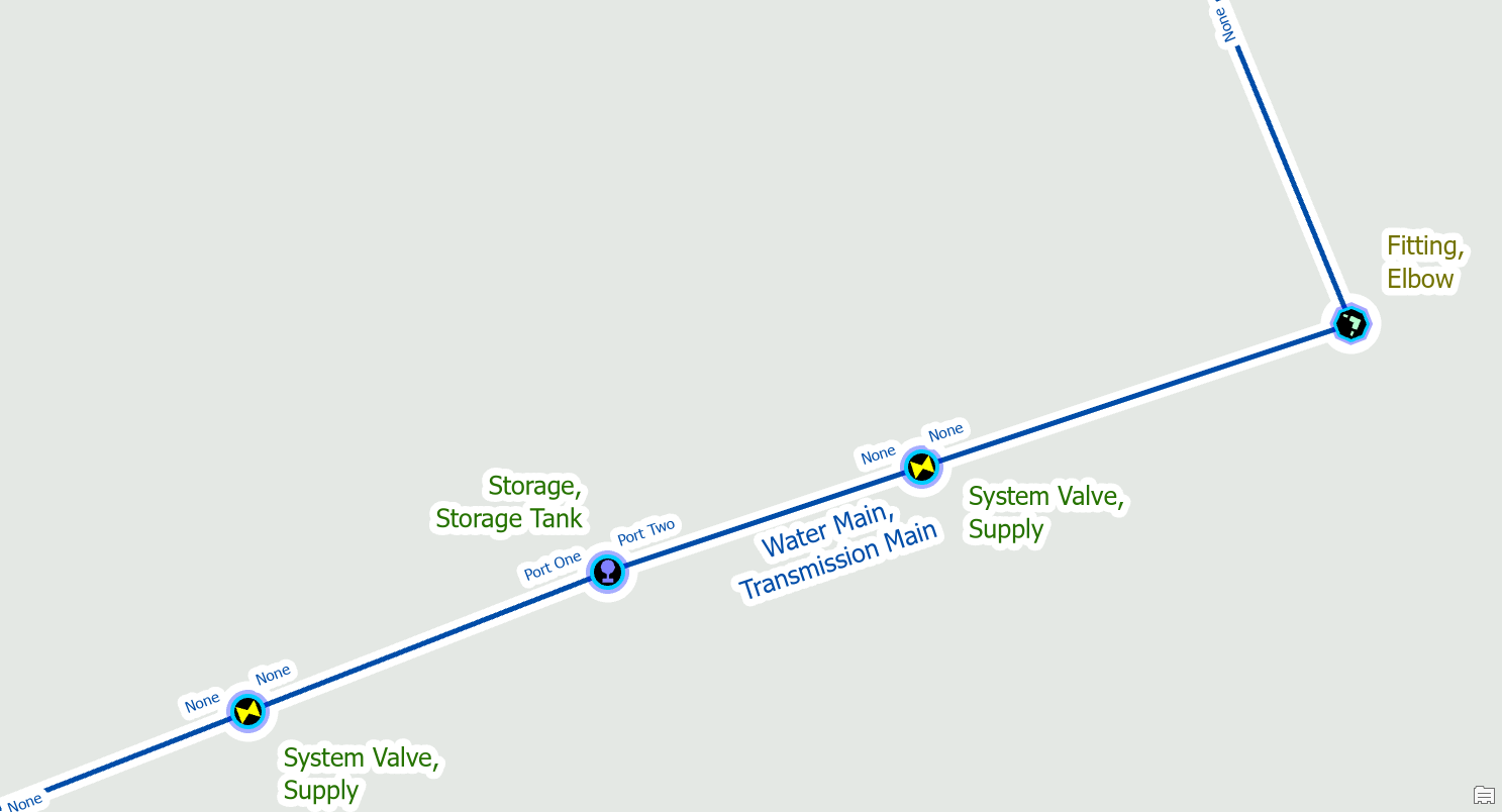
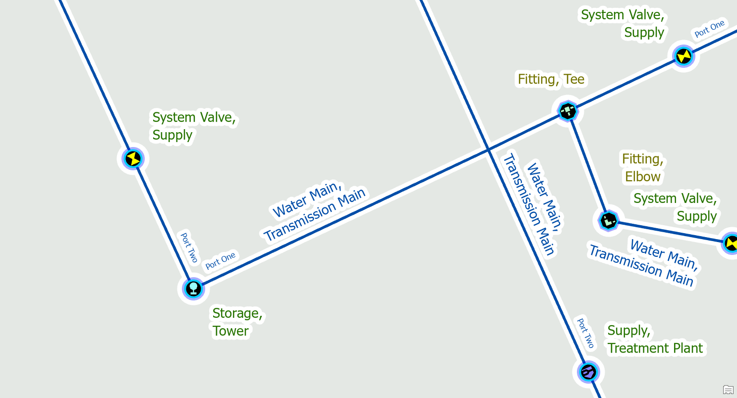
Move the device
Devices with terminals can only connect to the end of a line. In this example you can see that we’ve placed the water treatment at the intersection of two transmission mains.
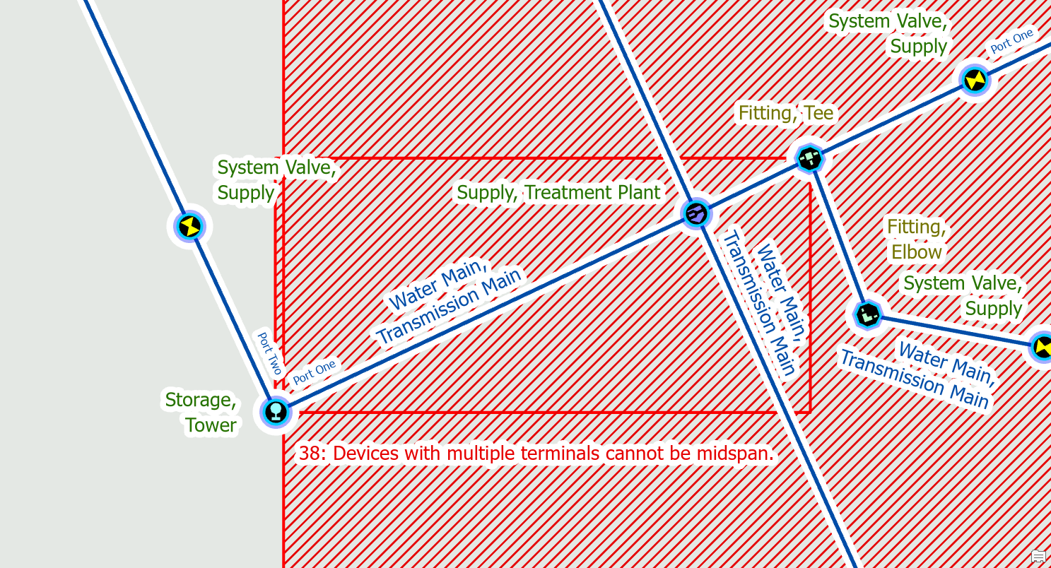
Before you split these mains we confirm whether the device is in the correct location and determine it should be moved first. Once we’ve moved the supply is in the correct location we split the line and assign terminals. We then use the modify terminal connections tool to connect the lines to the correct terminals on the device.

Commenting is not enabled for this article.