The various Utility Network Foundation packages available at ArcGIS Solutions offer the ability to jumpstart your network model of assets and configurations for distribution and transmission utilities, but what about plants such as power generation. Those facilities are complex systems with integrated and dependent networks that are required for successful operations. Last year I was asked; what do I do if I want a utility network, but I have infrastructure that’s not represented in a foundation package for the various utilities. In this specific case, the utility wanted to create network diagrams from a simple utility network that represented their critical assets for the plant cooling network.
Cooling systems are utilized in power generation to provide optimal steam regulation and turbine speeds, the excess heat is offloaded through pipes, pumps, and valves from the turbines to the towers. In many cases, those systems of pipes, valves, and coolers are represented for operators using schematics, sometimes hand-drawn. The ability to model that infrastructure in geographic space enables crews to have a greater understanding of hazardous workspaces and clearances for repair equipment (especially with the ability to project assets into the z-plane for 3-d renders).
——-Modeling plant configurations————
In this simple configuration, my goal was to build something quick but stable. While putting this demonstration together, my primary objective was to create a good schema of information that could be used to build a network diagram that represented critical assets. I was not worried about terminals (more about that later), controllers, or subnetworks and had no intention to provide directionality in the network that could not be configured using a trace parameter.
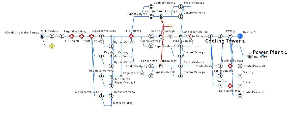
Now that I have that out of the way, let’s get back to the specific customer request that prompted the demo. The primary objective was to model the cooling infrastructure for a power plant. The customer provided me with an example schematic detailing the cooling systems for one of their plants. I could tell from a quick review of the schematic that many of the devices performed some type of action, things like valves, pumps, condensers, motors, or monitors. All of these ‘things’ could be added as asset types to preexisting asset groups already modeled in the template, I just had to add rules to connect the devices to pipes.
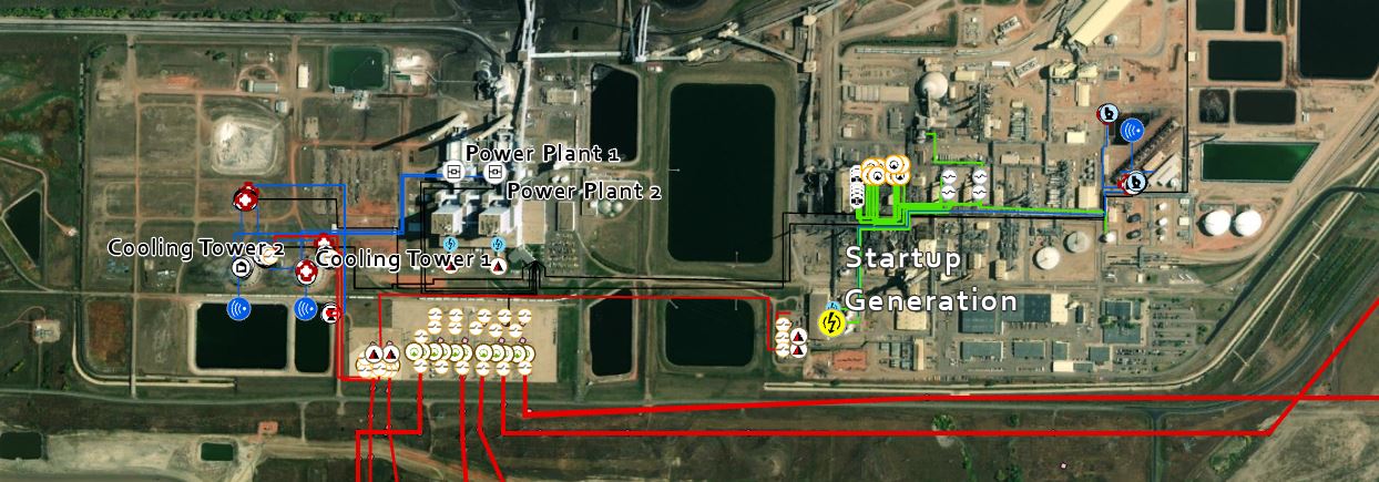
I was able to use existing pipe types to model cold water vs hot water pipe configurations and could use tees or connectors to model connection points. In just a few hours, using base map imagery of one of their local power plants, I had constructed a geographic representation of arrayed features that could be pushed into a utility network and diagrammed. This experience of using the foundation package as a starting point was much less painful than attempting to build a utility network from the ground up with an entirely new set of specific asset groups and asset types plus it gave me the chance to take this sample and build a more realistic model.
This model started with a water network to support cooling assets, I then added transmission lines and substation components with the help of Group Templates. For transmission lines, Group Templates enable the placement of the individual conductor, attachment points, or shield wire. For substations, Preset Templates from Selected Features can provide standardized assemblies of transformers, protective devices, and other elements that can be configured to represent substation configurations. Leveraging templates, other complex systems can be built for rapid and effective prototyping, in this example templates were helpful to build the startup generation fuel as a natural gas turbine. Of course, these configurations are very simple, but the point is to show that these networks could be utilized at all levels of fidelity. What’s really amazing here, is that the foundation templates from ArcGIS Solutions are adaptable to most utility configurations. If they don’t have specific assets or elements, they can be added. For more information regarding building utility network configurations, I strongly recommend attending the course Configuring Utility Networks in ArcGIS by Esri Training.
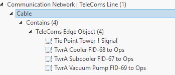
Finally, because this network was built using Utility Network Version 4 which supported nonspatial objects, I added a communication network to support the remote meter (AMI) and operational devices (SCADA). In this case, I had no intention of using subnetworks nor controllers, but I did add rules that would enable the creation of cross-domain associations. For example, I used junction-junction connectivity associations to connect operational devices for water cooling to communication receivers and to connect electric supply devices to cooling pumps, compressors, and chillers.
Before I go any further, it’s important to take a step back and delve into a bit more detail to note how all these new domains were applied using empty foundation template asset packages.
- We started with a water network and introduced additional asset types to represent the cooling network.
- To bring in the other elements of my network, I loaded schemas from the respective foundation asset packages (electric, gas, communication). Once again, I made sure to follow the golden rule, add but never ever delete!
- Adding the assets directly from the foundation package templates provided me with most of the network elements I needed to represent the new participating domains. While the bulk of my configurations were on the water/cooling network, most of the elements I needed were already modeled in the gas and electric networks. Enabling me to simply plug and play.
- Only a few rules were needed to run connectivity across the gas network to the electric turbines and from the electric service connections to the water pumps, and condensers.
The communication network offered an interesting opportunity to use nonspatial edges to represent paths from the remotely operated devices and meters to the plant control center. I plan on following up with more operational functionality and configurations in upcoming demos, but this was the first attempt to represent not only the state of the plant but to include in the model the collection of remote sensing data and the assets that support it.
While you may need to add new asset descriptions or a few additional rules to adapt your network to meet the needs of your business, building your networks on top of the ArcGIS Solution Templates gives you the opportunity to jumpstart your deployment. The same is true when you are interested in building networks with several domains.
Use the templates to build your supplementary domains as these will provide an advanced starting point to model the specific assets that support your business. I recommend building your design prototypes in a file geodatabase where you can quickly copy backups prior to changing the schema or network configurations. Because features assigned to different domains can still have connectivity, you have the option to configure those networks with cross-domain traversability. The enhanced tracing framework and named trace configurations give you the flexibility to not only sharpen the behavior of your multidomain traces but store and share the properties for repeatable testing and analysis.
Simple plant configurations provide insight into the primary elements of the facilities, but earlier this year I was asked about utilizing more advanced utility network capabilities inside of plants. Providing higher resolution configurations inside each plant component and providing deeper insight into how systems interact at the plant level brings value to engineers and executives and better visualizations to support the organization.
——-Higher-resolution plant configurations————
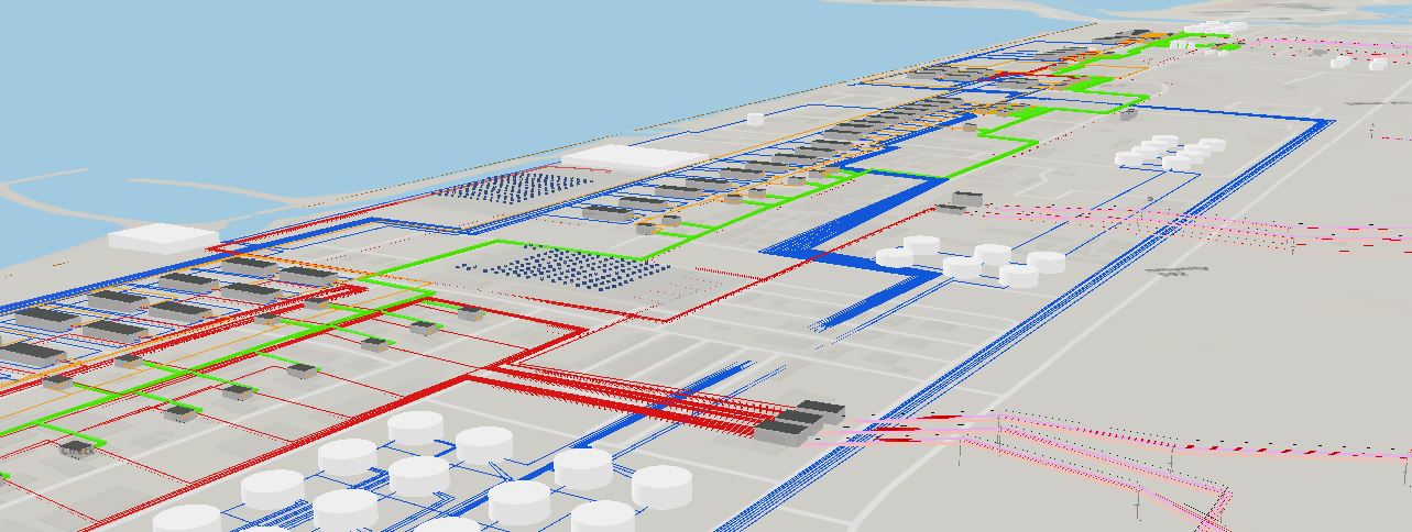
My next demonstration was to take a plant configuration, and leverage templates to model systems with greater complexities and deeper system integration. For example, the desalinization plant owned by Dubai Electric and Water Authority (DEWA) shown below, has onsite power generation via natural gas turbines. When you add in the remote metering and controls via a communication network you have all four domains (communication, electric, gas, and water) supporting the plant’s operations. The water network was used to support both water purification and fire suppression. The gas network provided fuel to the turbines, but also transported emissions for secondary turbines and finally to emissions storage onsite. The electric network provided power from turbines to water purification plants, to the transmission network, and integrated solar generation and battery storage for startup power. While this is not an operational model of the plant, it was designed to showcase the capabilities of managing these networks in an integrated system.

Like the power generation plant, this demonstration was configured to showcase business drivers in plants and other facilities. Asset management and scheduled maintenance can be tracked and managed at a higher resolution. Plant operations or events can be simulated, but most of all, the inherent 3D nature of utility network models enables users to better understand risks in confined spaces or hazardous operations. Elements of the plant were created using editing templates for the water plants, turbine houses, and substations, enabling higher resolution modeling based upon general layout designs. Much like network templates, these editing templates are used to provide me with a starting point. I can follow up and change the properties of any of the plant sites or facilities, but this enables me to get a quick start to deploy my plant.
——-Terminals————
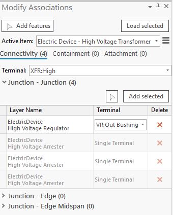
Earlier in this blog, I mentioned I was going to discuss terminals in a little more detail. In the utility network, terminals are an abstract that enables directionality through devices such as pumps, transformers, and valves. In the case of transformers, the terminals along with network rules regulate the connectivity of the appropriate conductor, where for example, a high voltage conductor is able to be attached to the high side of the transformer and a medium voltage conductor can be attached to the low side. What’s interesting here, is that the terminal is a true abstract, the ability to have terminals is configured and assigned to the device, but the actual terminal representation is stored in the line (in this case conductor) properties. In the case of terminals across the junction to junction associations, the properties are stored in the association.
All of these capabilities provide the ability to build and configure network models across a wide range of facilities, and organizations.
It’s exciting to see the diversity of implementations that are ongoing by our customers, distributors, and partners. Maps and applications address both common and unique challenges that utilities, facilities, and municipalities deal with every day. The ability to build rich models and experiences as a function of your assets requires a configurable network that can be tuned to represent and visualize outcomes of decisions.
Modern utility operations, planning, design, asset management, and construction teams support assets and networks where almost everything today has spatial context, and as a result, consideration of the terrain, environment, cultural features, and community needs all are impacted by the spatial location and reliability of utility facilities. The product of spatial insight is to leverage community and regional growth in a smarter and more sustainable way. For generation plants, having spatial context enables a richer context of the impact of system operations, provides better communication and visualization of planned operations, or the restoration of customer service during unexpected outages. Using a configured utility network with domains that impact your entire business will not only provide a more robust information system but enable a more collaborative environment with richer communication across operational teams that enable plant crews to respond to issues in a safer and more efficient manner.

Article Discussion: