When you find the shortest flight path between distant points, measure the true length of a flight path with multiple waypoints, or model the effective range of a directional antenna, the geometry you use needs to take the Earth’s curvature into account. Geometry that takes into account the curvature of the Earth is called geodetically-correct geometry, or geodesics, and it can be useful in a variety of Defense and Intelligence tasks.
The new Construct Geodetic tool in ArcMap lets you construct geodetically-correct geometry.
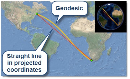
 For example, you can use the tool to create a feature showing the shortest flight path between Boston and Cape Town.
The geodesic line between Boston and Cape Town is the shortest distance between the two points on the curved surface of the Earth. A straight line drawn in most projected coordinate systems will diverge from this route.
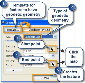
 The tool works in an edit session; first select the feature template you want to edit, select the type of geodetic geometry you want to create (in this case, a Geodesic Line), and click the start and end points (or type them). Click Create to finish the line, or click Add to add another geodesic line segment to the line.
Adding a segment can be useful when you are drawing a flight line with multiple waypoints; each segment will represent the shortest distance (following a geodesic) between each waypoint.
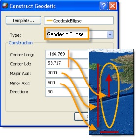
You can also create geodetic circles and ellipses. These may be used to represent range rings for aircraft, weapons, or directional antennas.

Measuring along geodesics
The Measure tool has been enhanced to allow geodetically correct measurements. You can use it to measure the distance between way points in a flight path, or the major axis of a directional antenna range ring.
With snapping enabled you can easily snap to endpoints or vertices of geodetic features for high accuracy geodetic measurements.
Geoprocessing geodetic features
 The Buffer, Bearing Distance To Line, Table To Ellipse, and XY To Linegeoprocessing tools can create geodetically correct features.
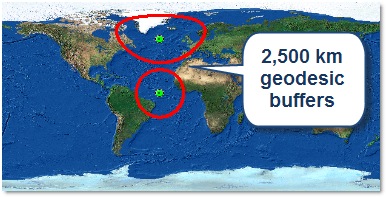
For the Buffer tool to create geodetically-correct buffers, the input geometry must be point or multi-point, the coordinate system must be geographic, and the buffer distance must be given in linear units. For more information on geodesic buffering, see this Help topic.
Storage of geodetic features
Geodetic features are constructed as curves using calculations based on your input parameters, but they are converted to standard feature geometry for storage in the geodatabase when you click the Create button. They’re stored in the geodatabase as a series of densely spaced vertices that closely approximate the geodesic on the GCS spheroid. Since they are densified, rather than parameterized (like arcs and Bezier curves), geodetic features don’t require any special treatment for storage in geodatabases.
Known limit
If you are designing an ArcSDE geodatabase in which you plan to store geodetic features, we recommend that you avoid using the MS SQL Server 2008 Geography type for feature geometry storage. The SQL Server 2008 Geography type can only store feature geometries that fit in a single hemisphere. This can cause unexpected results when creating or editing geodetic features, and makes the type unsuitable for storing large geodetic features.
Content provided by Dave McGuire
Commenting is not enabled for this article.