In our previous article, we discussed how Utility Network Subnetworks are configured for Gas and Pipeline pipe networks. In this article we are going to dig into the process of building the subnetwork and how to resolve some of the errors which may arise. If you’re interested in more content like this, I recommend you check out the Learn ArcGIS Utility Network for Gas and Pipeline learn series as well as these hands-on tutorials related to this article:
- Create and Manage Subnetworks
- Edit and Validate Subnetworks
- Perform Quality Assurance on Subnetworks
Gas organizations’ gas and pipeline pipe networks are constantly changing. When these changes occur, the Subnetwork representation of the System, Pressure, Isolation, and Cathodic Protection zones for the modified area need to be updated. The Update Subnetwork geoprocessing tool is used for this task. The Update Subnetwork tool checks for errors, populates the subnetwork name field on features in your subnetwork, and updates a subnetwork line layer with the extent and statistics of the modified subnetwork(s). You can learn more about the update subnetwork process on the Update a subnetwork page in the online help.
If the tool finds one or more problems with your subnetwork it will create errors in your database, often referred to as subnetwork errors. You can read more about subnetwork errors in the subnetwork error section of the online help. The purpose of this blog is to describe the most common subnetwork errors and their resolutions.
Below you will find an error with the most common error codes and their resolutions. The error type in this table is a shorthand description of the error code that users typically use when discussing these types of errors.
| Error Type | Error Description | Resolutions |
| Invalid Equipment | 24 / 26 / 40 / 41 / 42
An invalid network feature was discovered during the update subnetwork. |
1. If the affected features have been drawn correctly and should be allowed to participate in this tier of the network, then your geodatabase administrator can update your subnetwork definition to allow them to participate in this tier.
2. If the features are correctly classified and should not participate in this tier, then you will need to correct your data to prevent them from participating in this tier. |
| Inconsistent Network Controller | 29 – Inconsistent subnetwork name on multiple subnetwork controllers in the same subnetwork discovered during update subnetwork. | 1. If the features connected to each controller should be a single subnetwork you should update the subnetwork names associated with each controller to match.
2. If the features connected to each controller are different subnetworks and should be isolated from each other, you will need to determine why they are connected and update your data so they are isolated.
3. If only one of the controllers is active but they have different names then you will need to either isolate the backup controller from the active controller, or you will need to set the backup controller to not be a subnetwork controller. |
Invalid Equipment
Update subnetwork definition
Whenever a new type of feature is added to the utility network definition there are several steps you need to take to ensure the feature works properly in the model. In the topology error article, we mentioned the importance of adding connectivity rules to ensure that you don’t receive any connectivity errors. If you forget to add the feature to the list of valid devices, junctions, and lines for any tiers then you will receive an error when you run the update subnetwork tool and a subnetwork encounters one of these features.
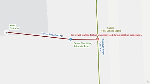
In the following example, we added a new asset type to our model “Metal Service Saddle” along with the corresponding connectivity rules that allow it to connect to metal distribution and service pipe.

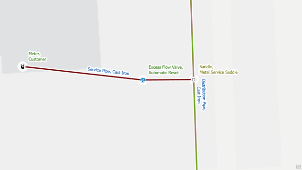
To correct the error, we add the new junction asset type to the list of valid junctions for all the tiers that we have in our model. In the case of the standard model, this means we need to add it to the system tier, pressure tier, isolation tier, and cathodic protection tier using the update subnetwork definition tool. Once we’ve finished adding it to all the tiers, we can then re-run the update subnetwork tool to clear the error.
Isolate the equipment
This issue resolution is only something you should encounter if you are on an older data model that has separate tier groups for gathering, transmission, and distribution. However, because this error often occurs with an inconsistent network name error even in newer models you should refer to the Isolate the Networks resolution for the Inconsistent Network Name error below.
Inconsistent Network Name
Update subnetwork name
System and Pressure subnetworks are typically designed to have multiple sources feeding them natural gas. As previously mentioned, in the Utility Network we refer to these sources as subnetwork controllers. The Utility Network understands that a subsection of the pipe network is intended to represent the same system zone or pressure zone when the subnetwork controllers have the same subnetwork name. If one or more of these subnetwork controllers (sources) has a different name from the other subnetwork controllers which were identified as part of the Update Subnetwork process, you will receive an error.
.
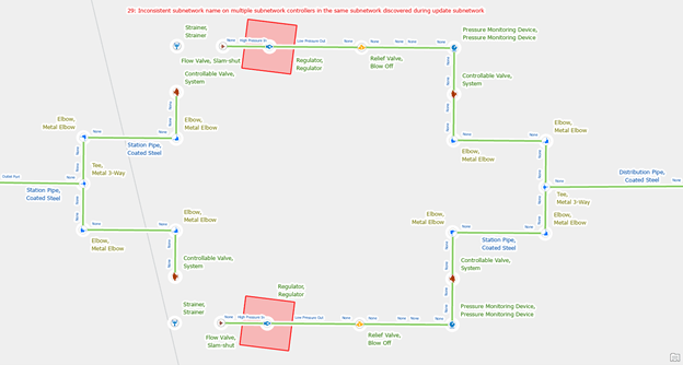
In the case of a pressure zone, if all the features are designed to operate at the same pressure level and are in the same area, then each of the regulators in the area should be configured to use the same subnetwork name. Each regulator will still need to have a unique subnetwork controller name.
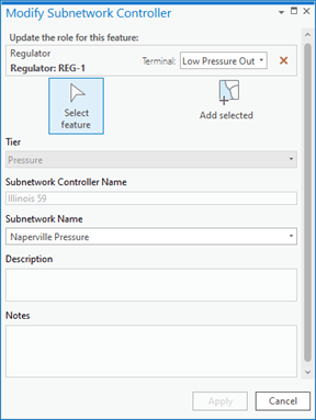
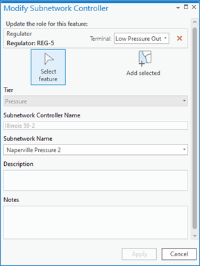
To correct the issue, use the modify subnetwork controller tool to remove the subnetwork associated with the regulator with the incorrect name.
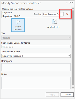
Then you can re-add a subnetwork on the low-pressure out terminal with the shared subnetwork name and unique subnetwork controller name.
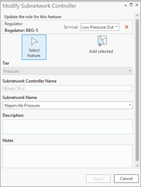
You will need to visit and validate each of the subnetwork controllers that reported this error, and once you’ve corrected and verified all the controllers you can then run update subnetwork to finish updating the subnetwork. If you attempt to update the subnetwork without validating all the errors, you will receive an error saying that one or more dirty areas were discovered in the subnetwork.
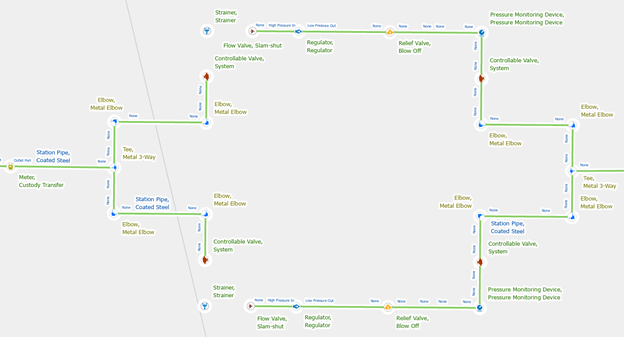
Isolate the networks
If you receive this error and the two subnetworks should be different pressure zones or systems, then you will need to identify how they have become connected.
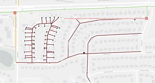
Run the shortest path trace between two of the network controllers that have errors to find the path between the two controllers. You can then review the pipes and devices along this path to determine where the problem is.
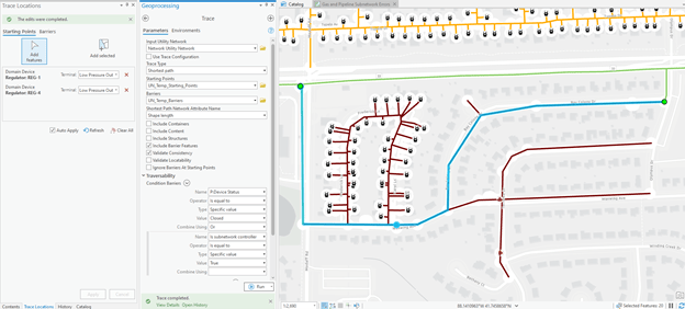
The most likely causes are pipes that are incorrectly snapped, equipment that wasn’t properly abandoned, or a valve that should be closed. Once you’ve identified and corrected the issue you should repeat this process until the trace can no longer identify any paths between the controllers.
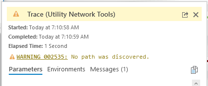
You should then be able to validate all the controllers and update the subnetwork.
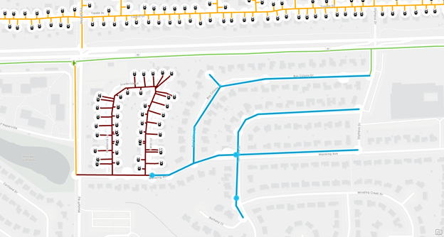
Remove the subnetwork
The last case is the rarest, but it occurs when one of the subnetwork controllers is an emergency or alternative source for an area but needs to have a different name.
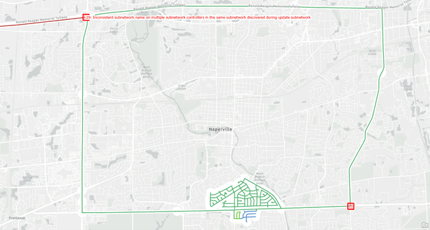
If this is the case, then you will need to either isolate the backup controller from the active controller, or you will need to set the backup controller to not be a subnetwork controller.
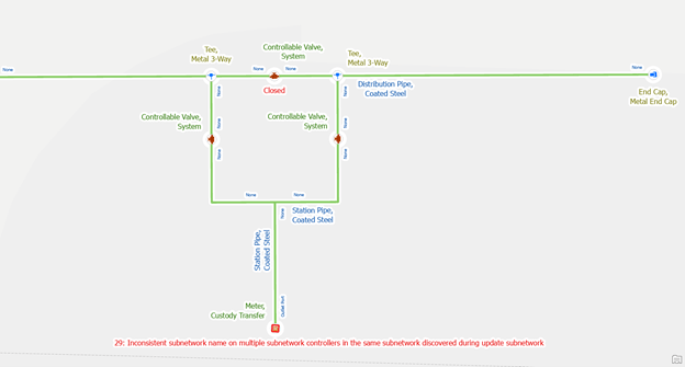
In the example above we reviewed the system with our engineers, and they let us know that the station with the interconnect is still being constructed and they need it modeled in the GIS for planning purposes. The engineers let us know that the valves at the station will be closed until the system redesign is complete, at which point the existing system will become two different systems.
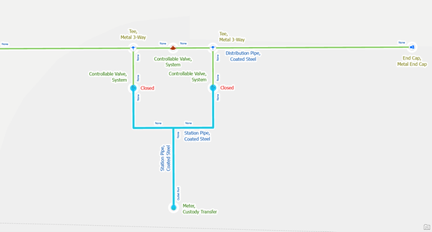
Next Steps
Now that you’ve read this blog you are well-equipped to deal with any errors that you encounter while creating and validating subnetworks for gas data. If you want to familiarize yourself with the gas and pipeline model, I recommend you download and familiarize yourself with the Gas and Pipeline Referencing Utility Network Foundation from the ArcGIS Solutions team. This solution includes sample maps and datasets you can use to explore the ideas discussed in these blogs.
In our third, and final blog in this series, we will show you some tips for performing data quality assurance on your subnetworks to make sure you’re getting the most out of your data! You will learn techniques to identify problems with your data that are not severe enough to cause an error but may result in some features not being connected to the correct subnetwork.
If you’re interested in more learning content related to the utility network check out the Learn ArcGIS Utility Network for Gas and Pipeline learn series as well as these hands-on tutorials related to this article:




Commenting is not enabled for this article.