This is the first in a series of articles where we look at the workflows associated with migrating data to a utility network and deploying it to an ArcGIS Enterprise environment. This article is focused on the data migration process using the Migration toolset. Read the Deploying a Utility Network Foundation article for information on how to implement a Utility Network Foundation. Read the Choosing the right model for you to learn about why you might prefer one of these options over the other.
These articles are designed to familiarize you with this migration process, help you understand the difference between the two approaches, and communicate the best practices associated with using these tools.
The process is outlined in three sections below, which are defined as:
- Data Migration – The process of creating a utility network from your existing data in a way that satisfies business requirements.
- Deployment – The process for creating the databases and services containing a utility network.
- Sharing – The steps you take after deploying a utility network to make it available to different users in your organization.
This article focuses on the data migration process, but you can find the rest of the articles in the series in the related articles section at the end of the article.
An important thing to remember about any project involving data migration, data modelling, or configuration is that these projects are often iterative. The steps outlined here will serve as the first iteration of many that you will work through as you refine your migration process, data model, maps, and begin incorporating the utility network into your business processes and system.
Data Migration
The first step to migrating your data using the Migration toolset is to make sure you have access to the tools. If you are using ArcGIS Pro 3.5 or later, these can be found from the Geoprocessing pane in the Utility Network toolbox. If you are using ArcGIS Pro 3.3 you can also access the tools, along with a collection of articles covering their use, by visiting the Get started with the Migration toolset article on the Esri Community site. If you’re using ArcGIS Pro 3.5 these tools, along with the Utility Network Migration Wizard, are included in the ArcGIS Pro install. You can try out the tools yourself in the Utility Network Migration Wizard tutorial or watch a short video demonstrating the Utility Network Migration Wizard.
The tool you will be using to perform the migration is the Migrate To Utility Network tool. This tool will create a new utility network based on the contents of your current geodatabase. This process is demonstrated below.
It’s important to remember that this is an iterative process as you run the tool for the first time. If you aren’t sure which layers to configure as controllers or which fields to use for asset types, you can skip over those steps and perform a second migration once you are more comfortable with the process and terminology.
The utility network created by this tool lacks the industry specific configuration associated with the Utility Network Foundations to address the more advanced capabilities of the utility network: however, these capabilities can be configured over time. You can learn more about how the Migrate To Utility Network tool works along with the capabilities and limitations of the utility network it produces by reading the following articles:
- Introducing the Migration toolset for ArcGIS Utility Network
- Building your Utility Network
- Choosing the right model for you
In addition to creating a utility network, the tool also creates a series of layers to help visualize the utility network it created. In the Sharing section of this article, you will learn how to use this layer to recreate your maps for desktop, web, and mobile applications. The most important thing for you to understand about the migration process is how it preserves the classes, fields, and domains from your source data. The video below shows an example of this for a water model.
Once your data is migrated to a utility network you are ready to identify and correct any topology errors that exist in your data. This is an essential part of implementing a utility network because the utility network cannot perform tracing or analysis in areas of a network that contain errors. If you do not fix these errors, you will not be able to satisfy any business requirements related to tracing and analysis. It also means you will not be able to be able to identify features that are disconnected in your network, a vital form of quality assurance for any network dataset.
Fortunately, the Migration toolset includes tools to help you identify and resolve your topology errors through automation. The first step of this process is to run the Analyze Network Data tool to identify any problems with your utility network data. You can learn more about this process by reading the Analyzing Topology Errors article. The video below demonstrates how to use this tool to create a database that summarizes all the errors in your data.
In addition to reviewing the layers and charts created by the tool, you can also populate an Error Resolutions table to provide instructions that an automated data cleanup tool can use to resolve your errors. The Migration toolset includes an Apply Error Resolutions tool that provides automated resolutions for the most common types of error resolutions, read the Resolving Topology Errors article for more information on this process.
Errors that impact your current data, like invalid geometries or stacked point features, should also be corrected in your source database. You may decide to rely on automated resolutions to resolve issues like missing junctions that you cannot resolve in your source data, or that do not affect your current workflows.
The primary purpose of the migration database for the first few iterations is to refine your data mappings, understand issues with your source data, and improve the final data quality of your migrated utility network.
The video below demonstrates how to specify a resolution for an error along with how to run the tool to correct the error.
Once you have applied automated resolutions for all your topology errors you are now ready to enable the network topology. This will validate all the features in the network and creates error features for any remaining errors.
If you find you have many errors, this is likely because:
- You didn’t provide resolutions for all of the error types in your database.
- Your utility network contains errors that the Analyze Network Data tool does not currently support using automated resolutions (e.g. associations).
If you find you have many errors in your network, you can use the Summarize Utility Errors tool to create a report of the remaining issue. Even though this tool doesn’t provide any automated cleanup, viewing a report of all your errors can help you identify a solution. In some cases, they may be caused by a problem with your data migration, and in other cases they may just be data quality issues you need to fix manually. You can find a video below of how to run the Summarize Utility Network Errors tool:
If you have a large number of Ambiguous Connectivity errors that you believe are caused by missing terminal assignments, you should consider using the Assign Terminal Connections tool included in the UN Package Tools. This tool will automatically assign values to the FromDeviceTerminal and ToDeviceTerminal fields to all lines connected to devices that have terminals. However, because the tool uses spatial analysis to determine these values, and not network tracing, carefully review should be performed for any assignments made to devices with directional terminals (pumps, pressure reducing valves, etc) to ensure the upstream/downstream terminals are set correctly.
Once all your errors are resolved you will then create one or more subnetworks. This will allow you to identify any disconnected features in your network caused by improperly drawn or snapped features. The video below demonstrates manually creating a subnetwork and identifying disconnected features.
If you didn’t initially select at least one class to serve as a controller, you should consider going back and repeating this process with that option selected. Creating subnetworks will allow you to identify features that are disconnected in your network, which is an important quality assurance check that is used to identify data cleanup tasks that can be worked in parallel with your migration.
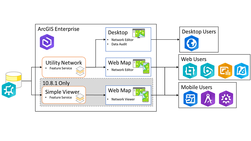
As you prepare to deploy your utility network to ArcGIS Enterprise, there are several things to consider before recreating your maps for use in desktop, web, and mobile applications. These are discussed in the next section.
Recreating maps
Most client-applications that interact with ArcGIS Enterprise access data using a web map. A web map contains a collection of layers from one or more services that is typically overlaid on a thematically appropriate basemap. The feature service itself provides access to the data, but all the symbology, labeling, etc are defined in the web map. This approach makes it easier for administrators to manage larger deployments, since they only need to maintain a relatively small number of services while also allowing end-users to have the flexibility to create and style their own maps.
Migrating to the utility network requires making schema changes that must be reflected in your maps. The Migration toolset minimizes these changes by retaining many of your fields and domains, but you will need to create new maps that use the new layers in your utility network feature service while retaining as much of your original symbology, labeling, etc as possible.
The video below shows how you can use the layer created by the Migrate To Utility Network tool along with a map document for your source data to recreate the labeling and symbology in your utility network layers.
Note: The ability to paste the symbology or labeling from a feature layer to a subtype layer requires ArcGIS Pro 3.4 or later.
If you want to know more about the best practices for creating your own maps for utility network data, check out the Configure a map for ArcGIS Utility Network tutorial. It shows you many tips and tricks while also demonstrating the importance of using subtype group layers, a feature new to ArcGIS Pro that is essential to creating performant maps for datasets like the utility network.
Conclusion
If you’ve followed these steps, you will have created a fully connected, traceable utility network in a mobile geodatabase suitable for prototyping and testing different workflows with the utility network using ArcGIS Pro with a single user. Once you’re ready to take this to the next level and use the utility network in web and mobile applications, you should read the Deploying to ArcGIS Enterprise article.
The processes outlined here are just the beginning. Here are some other things you should consider doing with your model:
- Go back and define asset types and a network controller layer if you haven’t already.
- Improve your data quality by Refining your connectivity rules.
- Review the existing fields in your model and consolidate similar fields or remove unused fields.
- Use the Utility Network Package tools to create a repeatable data migration process. Learn more in the Migrating data to the utility network article.
This article is part of a larger series of articles explaining the process and best practices for migrating and deploying a utility network. You can find the other articles in the related articles section below this post. If you have any questions about this content, or want more specific information, please post a question on the ArcGIS Utility Network community site.


Commenting is not enabled for this article.