By Aileen Buckley, Mapping Center Lead
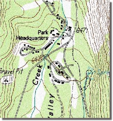
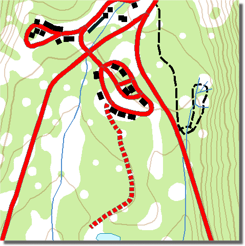
The map excerpt shown at right (click on it to see the details) shows an example of hollow cased roads. The map is from a mosaic of USGS DRG image files. The map specification requires that the cased road symbol contains a transparent gap. The examples shown below were created with ArcMap 9.2 and used cartographic representations to re-create the effect on the USGS DRG map.
A simple two-layer cased line symbol won’t work, as there’s no way to define the center portion of the line as ‘no color’. A white center would not look right as it would block out any information below the roads in the map’s drawing order
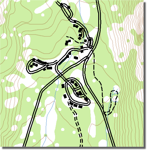
You might try to use a two offset thin line symbols, but there’s not an easy way to cleanly merge and join features such that the lines don’t look cluttered and disjointed. Also, note the dangles in this example (on the right); it’s difficult to control the side to which side the lines will offset. Worse still, offsetting line symbols has a high cost for your CPU, it seems the better we get at figuring out how to draw offset symbols the slower they draw.
The solution is to create a masking layer. The geoprocessing tool used to achieve this effect – Feature Outline Masks – has been available since version 9.0, and requires an ArcInfo licence.
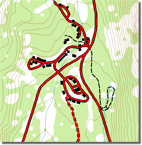
The tool’s Reference Scale property should be set to the scale your map will be printed or used at. The tool’s Margin property should be set to 0 (zero) for this particular effect. You would set the margin if you wanted to create a mask that acted as a ‘buffer’, i.e. outside the road symbol. The idea here is to first create some temporary symbology for your roads. Choose a cased line symbol and remove the bottom layer (the casing) from the symbol. Next, create masks for your roads layer using this temporary symbol. Then for your layer’s symbology, just use the casing layer of the symbol. In the example shown below, the red layer is the polygon output from the Feature Outline Masks tool.
Example using red cased line (remove the casings prior to creating the masks)
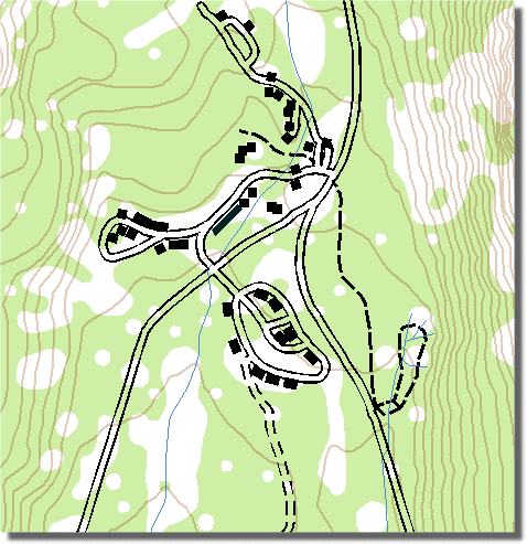
Resulting masks are now used on just the casings
Creating masks for cartographic representations
You can use the Feature Outline Masks tool on cartographic representations too. The key difference between using the tool on standard symbols and cartographic representations is that with representations more of the symbol is masked, specifically, dash patterns and markers in marker lines. Note the image below: a dashed line was masked to create the ‘unpaved’ road symbol.

Article Discussion: