Introduction
Update: ArcGIS Pro 3.5 added new tools to bulk apply error resolutions to topology errors. The concepts outlined in this series of articles are important to understand when choosing which actions to use when resolving your errors. Learn more about how to use these new tools by reading the Analyzing topology errors and Resolving topology errors articles.
The first time you run the validate topology tool on your utility network and encounter a topology error you will likely ask yourself three questions:
- What caused this error?
- How can I fix this error?
- What can I do to prevent this from happening again?
The purpose of this article is to provide the industry specific examples of the most common errors, so you are better equipped to answer these three questions. The different resolutions aren’t always immediately obvious, and we hope this guide will help you quickly identify the best solution for your data and your specific situation. If you’re not already familiar with error management in the utility network, you will want to familiarize yourself with the following resources:
- You can find a full list of all the possible network errors on the Errors topic in the online help.
- Read the Feature restrictions and rules topic to learn the difference between a network rule and a feature restriction, along with the constraints for what types of features can be connected or associated.
- Read the Dirty area management with the utility network article to learn how the utility network uses dirty areas to track and validate edits made to the network topology.
- Read the Managing Topology Errors article for a higher-level overview of error management.
You can find more electric utility network related content in the ArcGIS Utility Network for Electric reading list. You can also try these hands-on tutorials related to this article:
- Fix Connectivity Errors in a Utility Network
- Fix Topology Errors in a Utility Network
- Configure rules for a Utility Network
You can use the following links to quickly navigate to the different errors:
| Error Type | Error Description |
| Junction-Edge Errors | 8: Invalid connectivity – No junction edge rule |
| Ambiguous Connectivity | 9: Invalid connectivity – More than one junction edge rule applicable |
| Edge-Edge Errors | 10: Invalid connectivity – The edges are different subtypes and cannot connect |
| Stacked Points | 25: Stacked point features |
| Invalid Terminal Connections | 36: The line feature has an invalid terminal |
| Midspan Terminal Devices | 38: Devices with multiple terminals cannot be midspan |
Junction-Edge Errors
Fix Incorrect data
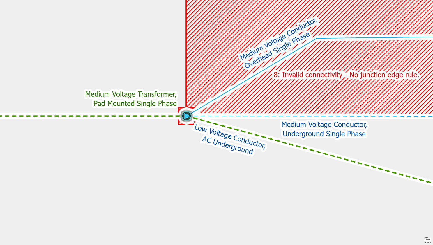
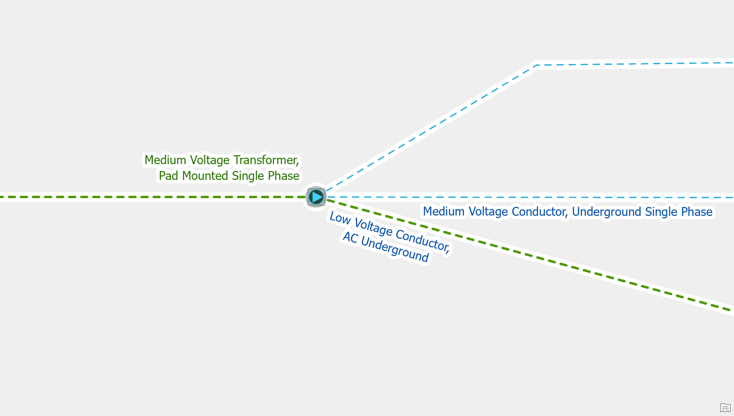
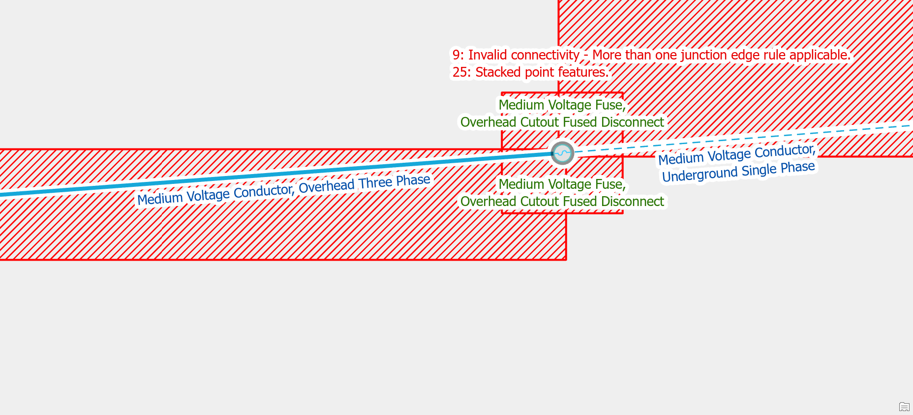
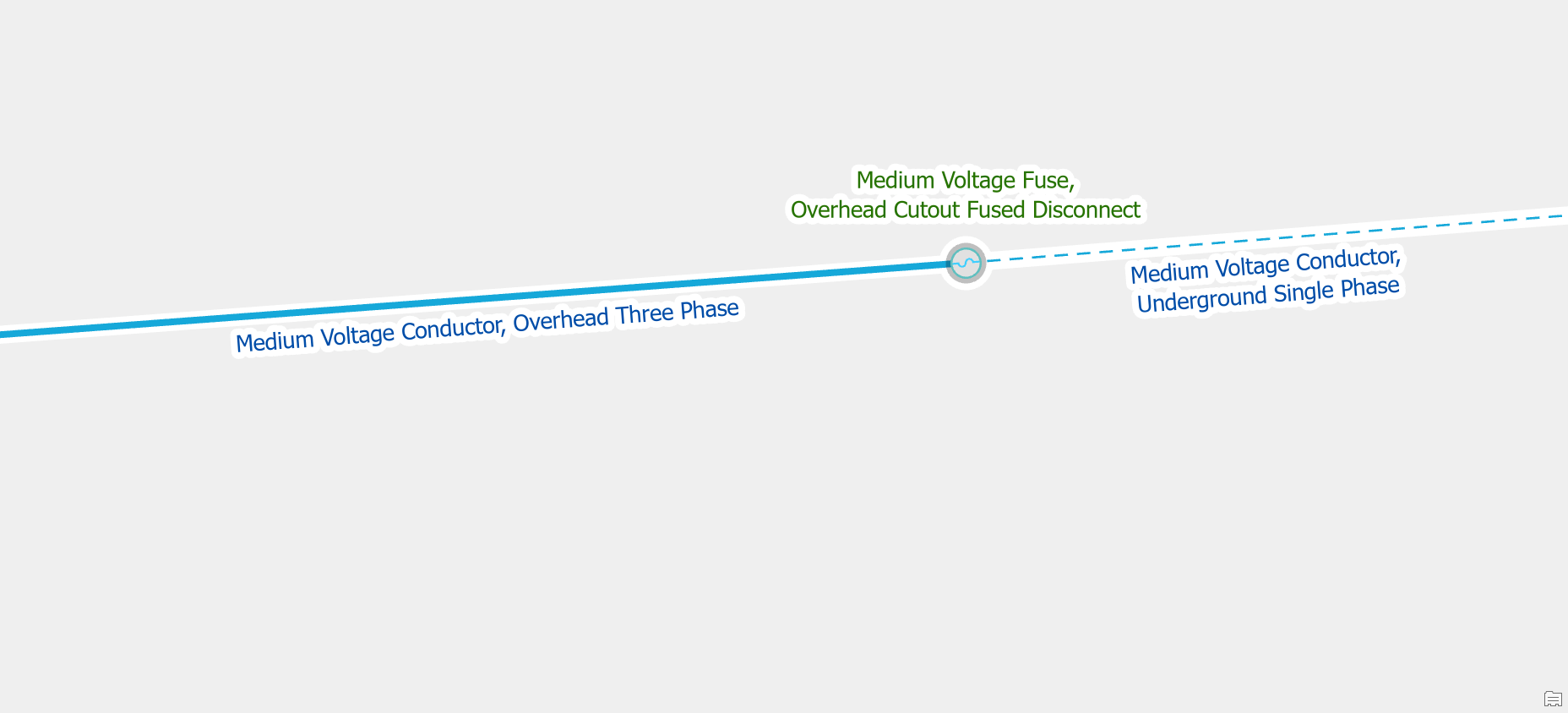
If you convert an area from overhead to underground but you forget to update the asset type of one of the lines or devices in the area you will get this error. In this example you can see that one of the conductors wasn’t updated to be an underground conductor. Correct the asset type to be underground single phase to resolve the error.
Add a rule
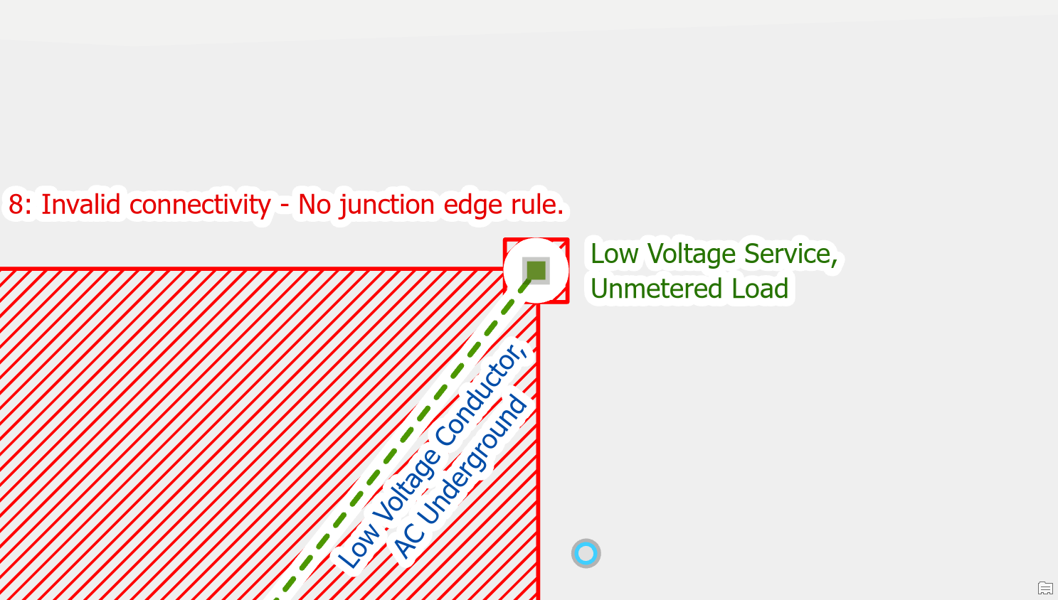
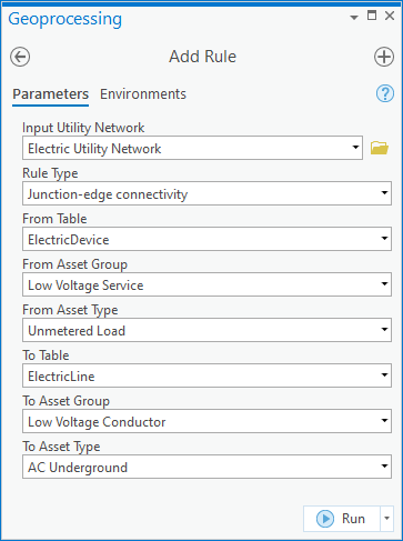
If you add a new type of device to your data model, in this example unmetered load, but you forgot to add rules you will receive an error when you place the new feature type. To fix the error an administrator would need to add the rule(s) required for the new type of feature to allow it to connect to different lines, junctions, devices. The administrator would also update the subnetwork definitions to allow the new equipment to participate in different tiers of the network.
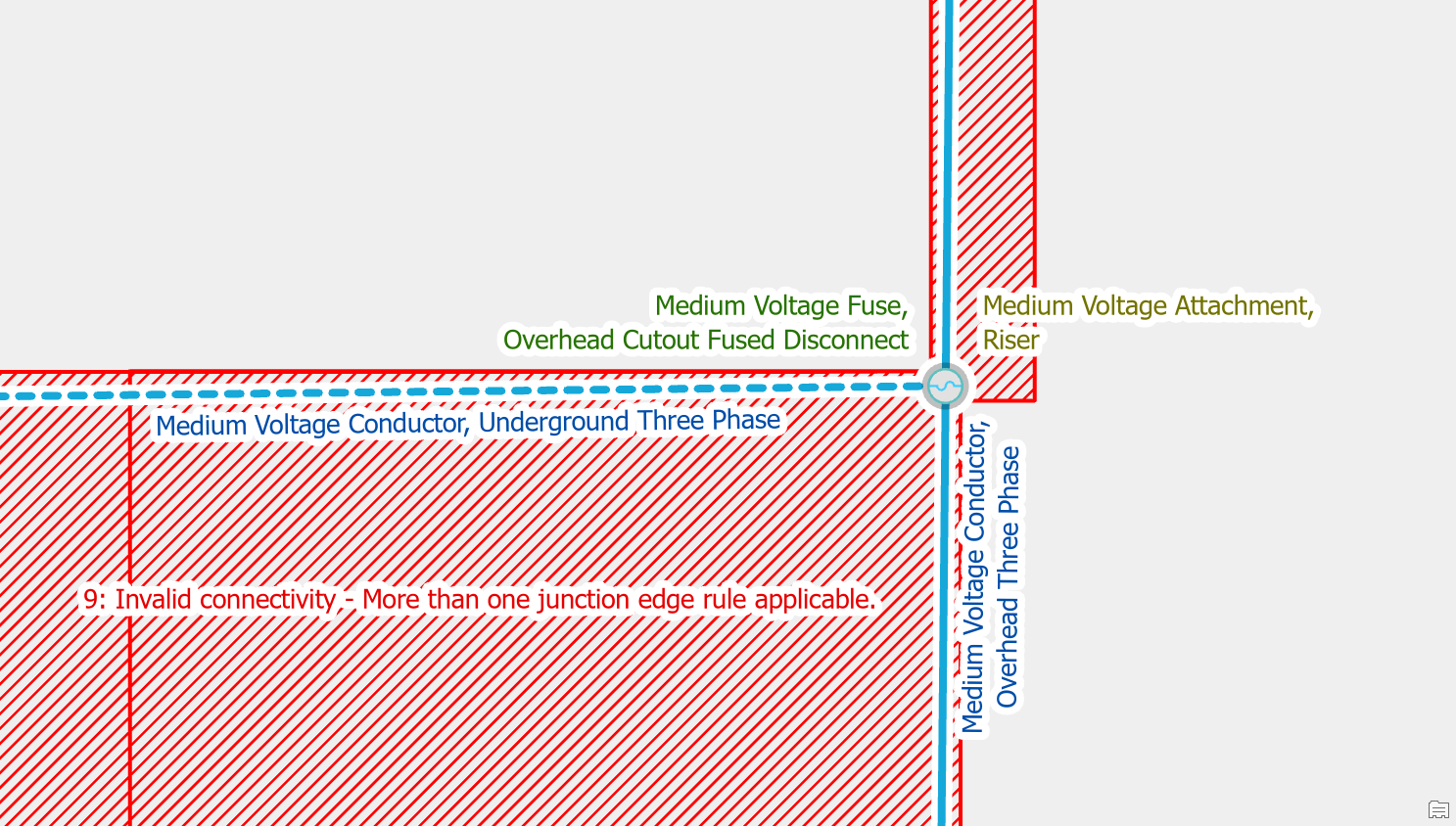
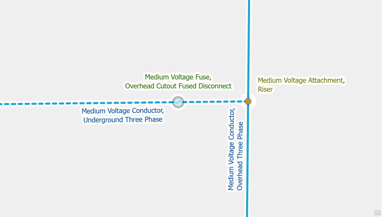
Ambiguous Connectivity
Use Modify Terminal Connections pane
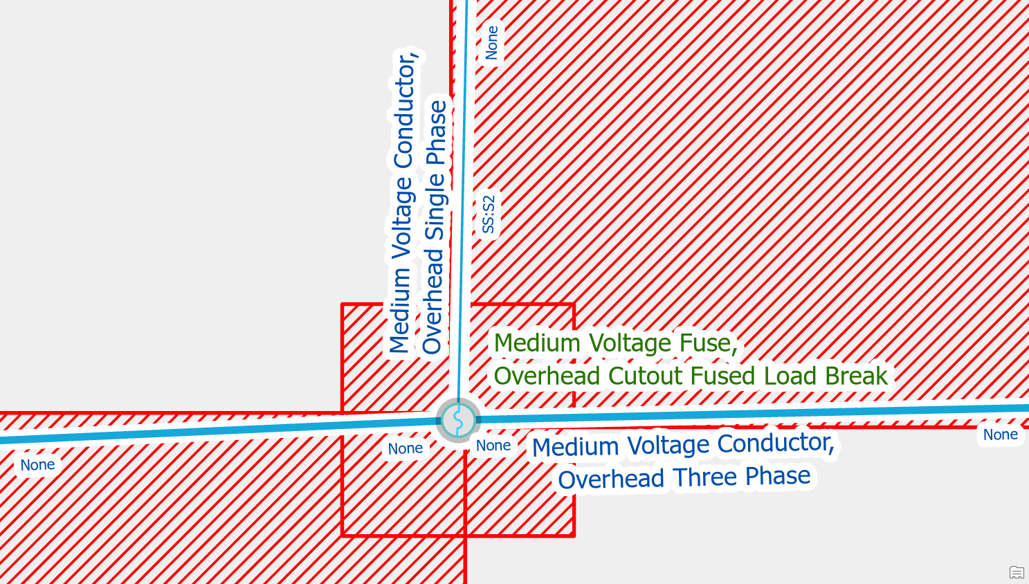
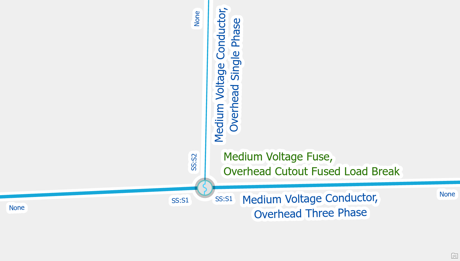
When load breaking switches are placed at the end points of two lines you need to say which terminal each line is connected to. To correct the error you use the modify terminal connections tool on the each line to connect each line to a different terminal. It’s important that each line is connected to a separate terminal so the switch will stop flow when it is opened.
Remove the invalid rule
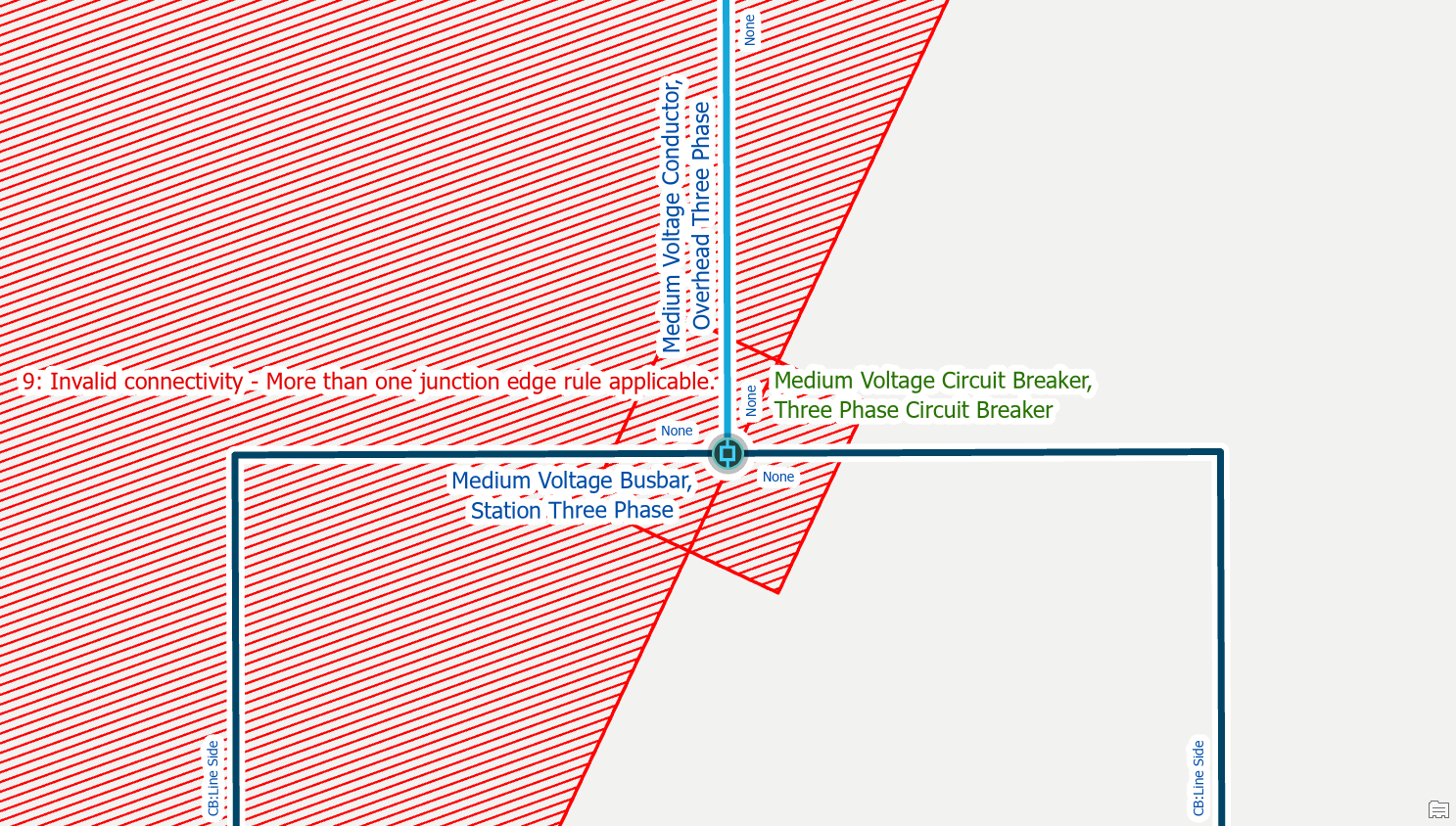
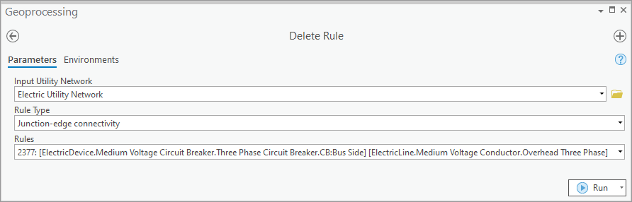
If you see terminals available for connection that should never be used in your model, like connecting an overhead conductor to the bus side terminal of a circuit breaker, then an administrator should remove this rule from the network. To correct the issue, have an administrator remove the invalid rule and the issue should go away. Because there is only one terminal that the line can connect to it will automatically connect to the correct terminal on the device without the editor needing to use the modify terminal connections tool.
Move one of the features
If you have two valid point features that are connected to a line, but the features happen to be stacked on top of each other, you will need to move one of these features. A common example of this is when placing a riser and a fuse on the same pole. To correct the error you will want to move the riser off the pole.
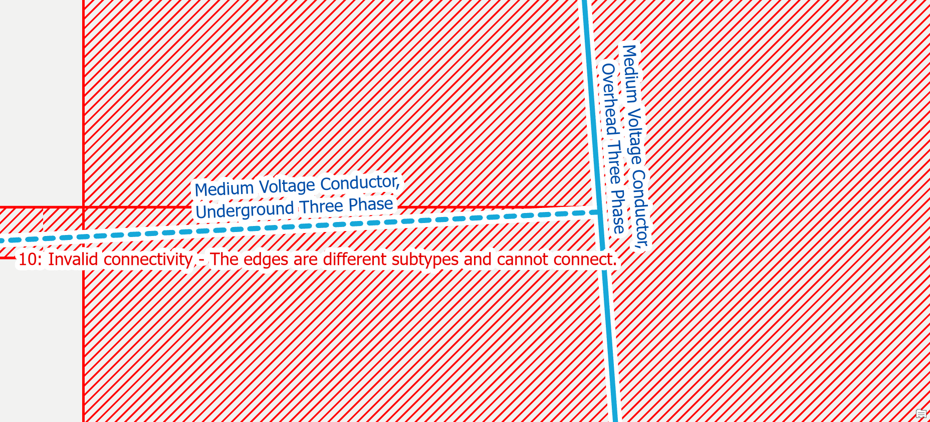
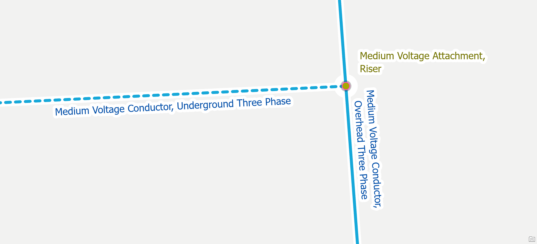
Edge-Edge Errors
Create a point feature
If you have an overhead conductor connected directly to an underground conductor without a device or junction then you will also receive an error. You can clear the error by creating a riser between the lines. You should then get a crew to verify whether there is also some kind of device at the location like a fuse or disconnect switch, especially if the line is part of the backbone of the circuit.
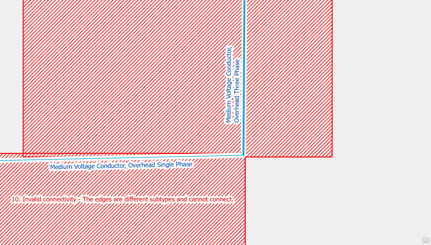
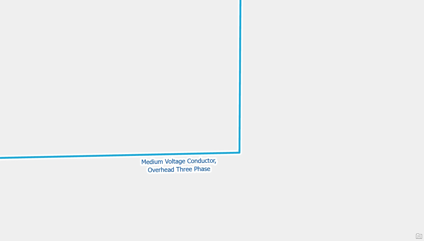
Edit the features to match
This error will often occur when a feature is improperly classified. A simple example is a conductor with phasing ABC but an asset type of single-phase conductor that is connected to a three-phase conductor. In this case you should update the classification of the single-phase conductor to be three-phase. This was caused by a conversion or data entry issue.
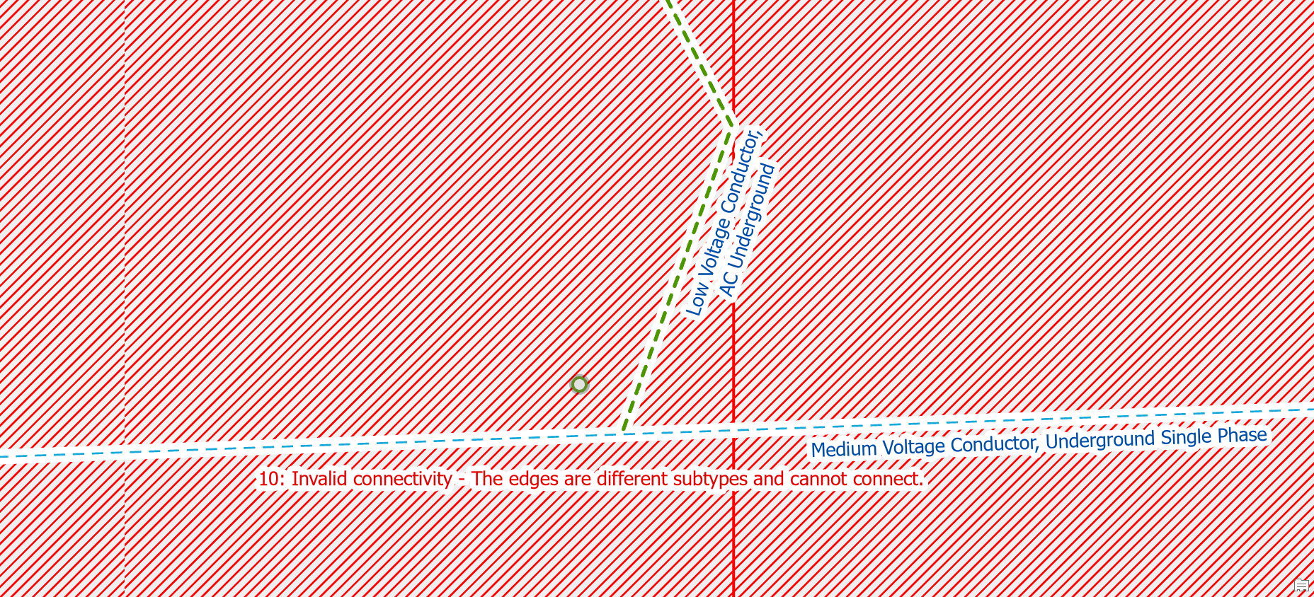
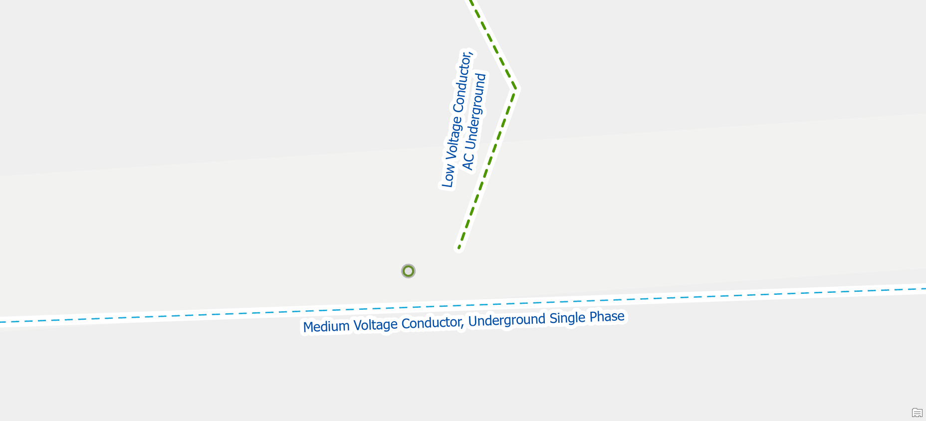
Move a line
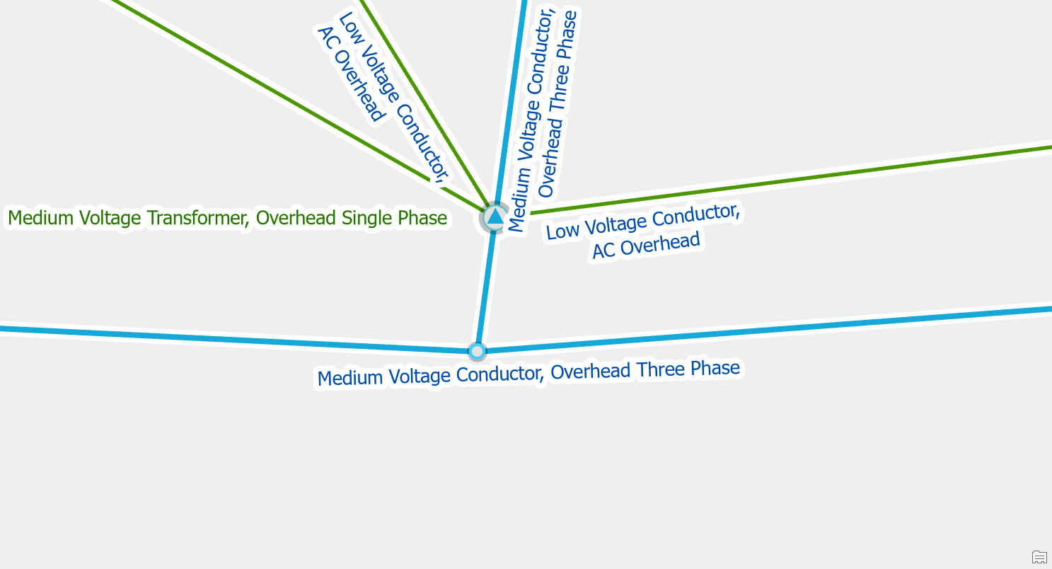
If you have a low voltage conductor connected directly to a medium voltage conductor, you receive this error. If the low voltage conductor energized from a transformer in another location, you should update the geometry of the line, so it no longer connects to the medium voltage conductor. If the low voltage conductor is energized from this location, then you should still disconnect the low voltage line, but you should investigate whether this secondary actually exists in the field and where the transformer is that it is connected to.
Stacked Points
Delete one of the stacked features
If you look at the two features and they appear to be duplicates than you should delete one of them. This will sometimes happen when an editor accidentally places the same feature twice.
Move one of the features
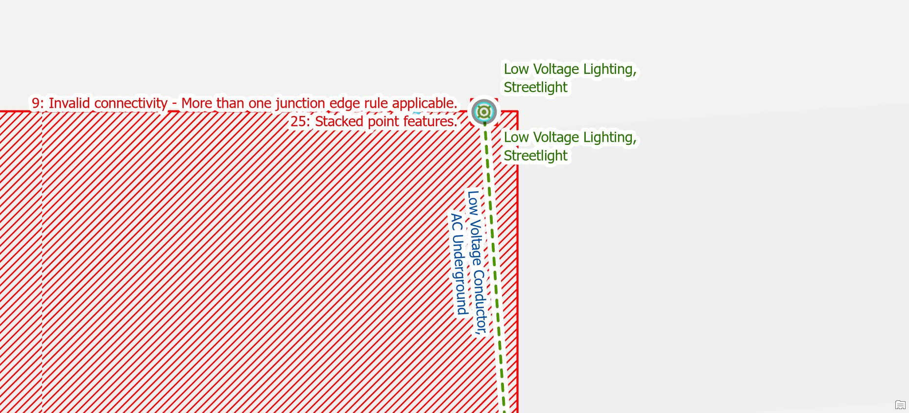
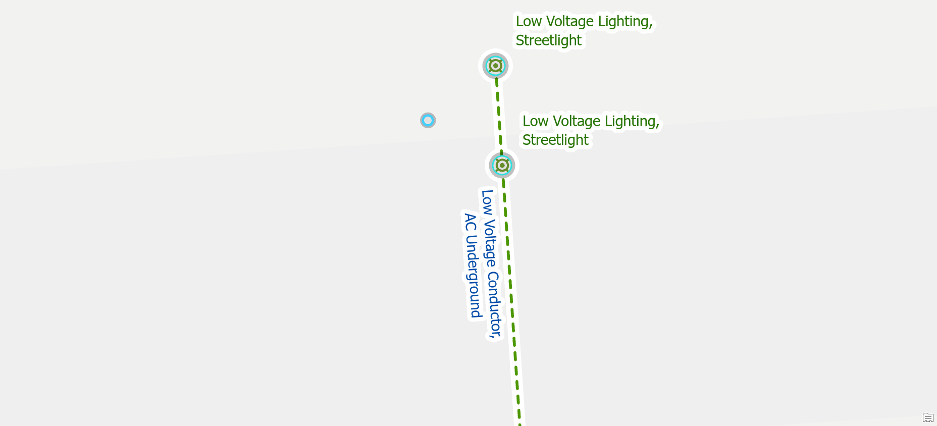
If you have two streetlights attached to the same pole, then you should disconnect and move one of the streetlights from the pole. If you energize your streetlights, you should either move the second streetlight along the secondary or create a new piece of secondary to ensure it stays energized.
Invalid Terminal Connections
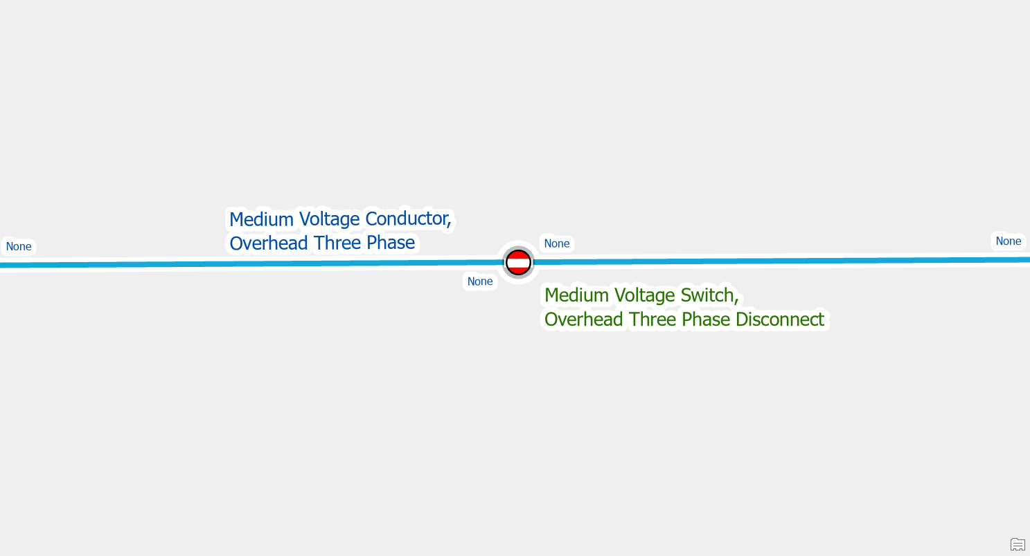
Reset terminal connection
Terminal connections are stored on the line features that connect to devices. This means when you move, delete, or replace a device with terminals the line will still have attributes that reference the terminal from the previous line. A simple example of this is replacing a load breaking device with a disconnect device, because the original devices have terminal connections, and the new ones don’t.
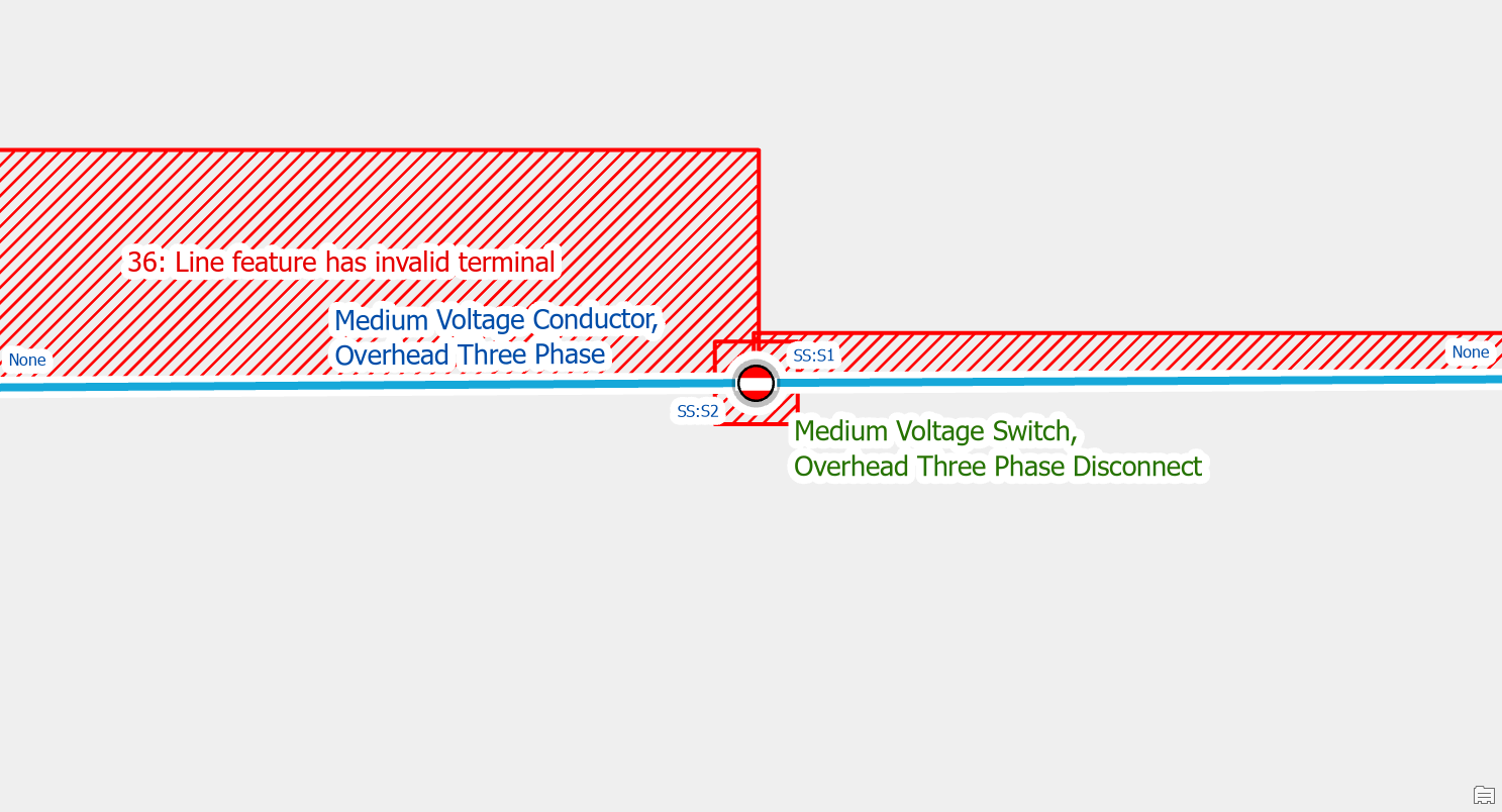
To fix this error use the Modify Terminal Connections pane to correct the terminal connections on each line, removing any invalid connections.
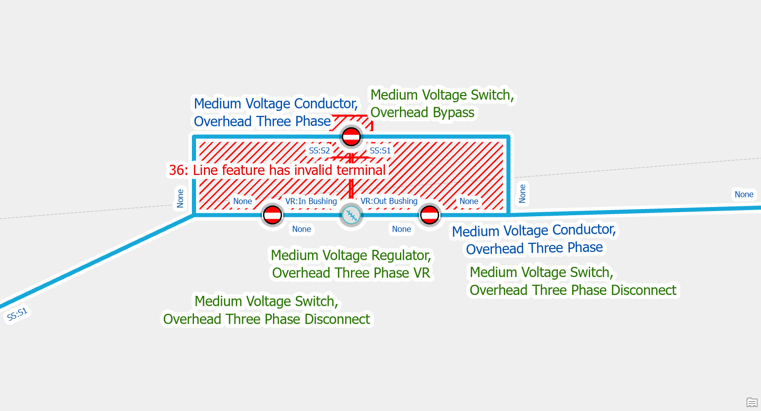
Connect new terminal
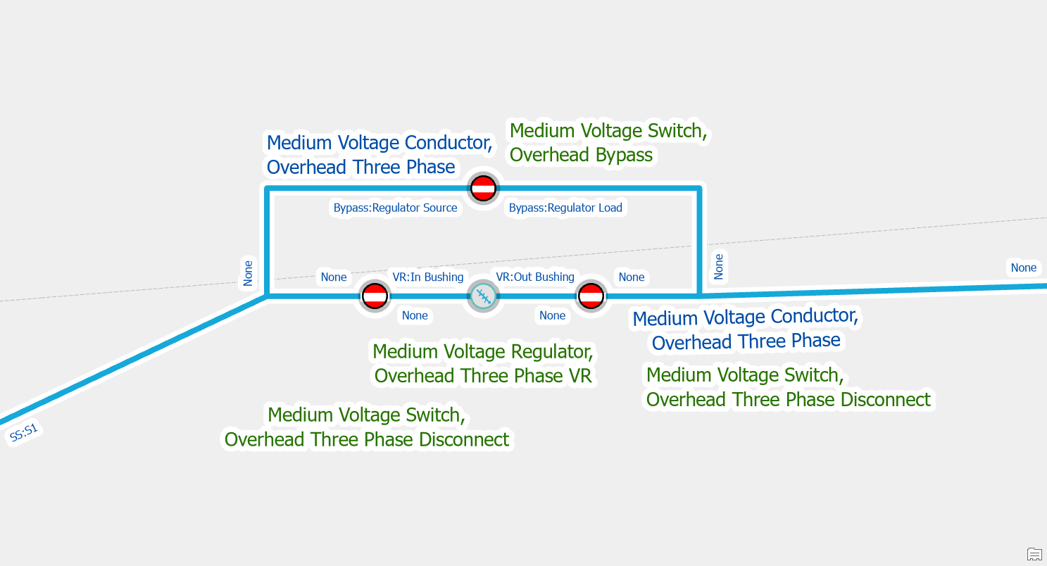
If you replace a device with terminals with a device that has a different terminal configuration you will also receive these errors. This will occur if you decide to replace load breaking switches with more sophisticated switches like bypass switches or T/V blade switches, since each of these switches has a different terminal configuration.
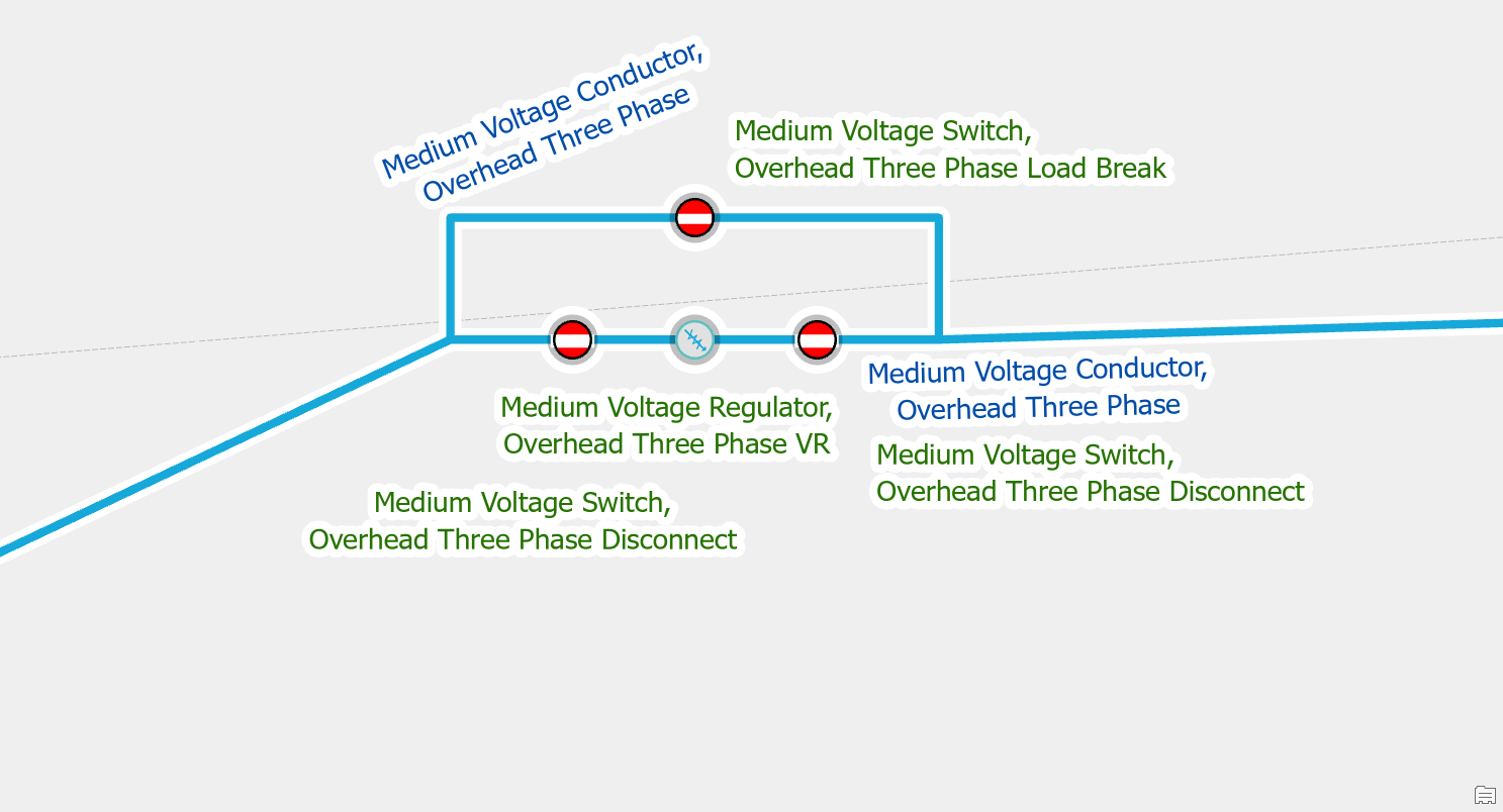
Before you can use the modify terminal connections tool to assign the correct terminal you must manually set the terminal field, fromterminal or toterminal, to the value of “None”. Once you’ve reset the terminal connection you can then use the modify terminal connections tool to assign the new terminal.
Midspan Terminal Device
Split the Line
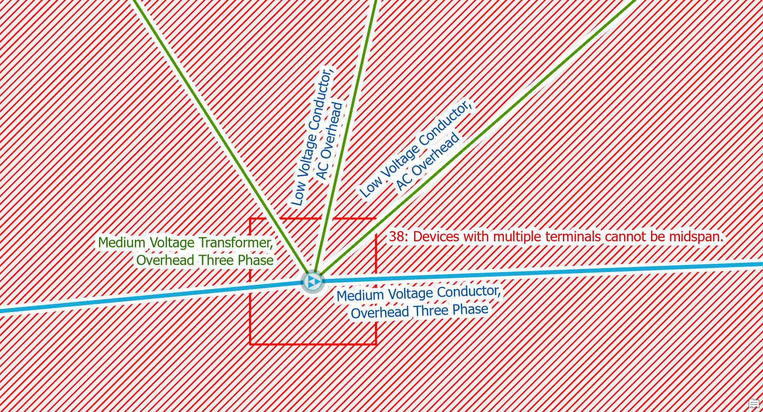
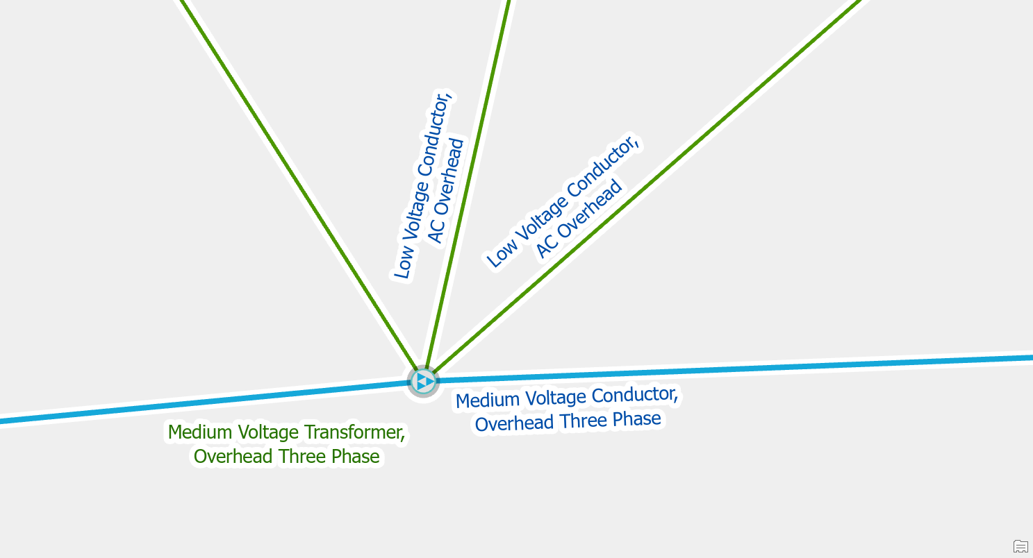
If you place a device with terminals on a line without splitting it first, you will receive this error. If you place devices directly on lines you will encounter this issue when placing transformer or load breaking devices. To fix the issue you use the edit tool to split the line at the location where the device connects to the line. If you get an ambiguous connectivity error (type 9) after you’ve split the line you need to use the modify terminal connections tool to connect the lines to the correct terminals on the device.
Move the device
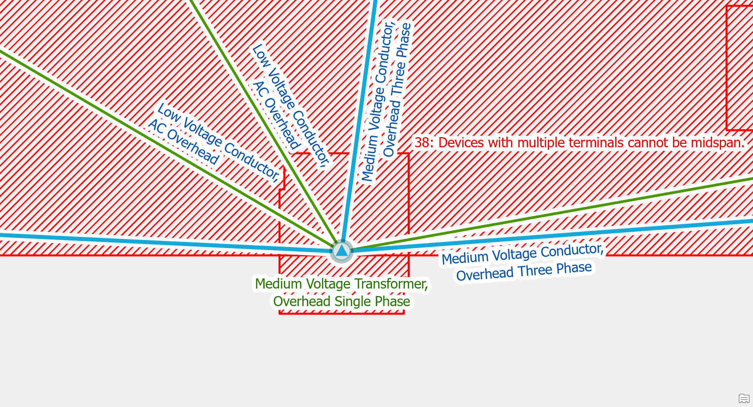
Before you split the line you should make sure the device is in an ideal location, since it will split all lines connected to it. In the case of fuses or switches on tap-lines, you will want to make sure the device only split the tap-line and not the main-line.
After you’ve moved the device and split the line you will still need to use the modify terminal connections tool to connect the lines to the correct terminals on the device.


Commenting is not enabled for this article.