With the growing popularity of 3D visualization and mapping, some users are transitioning from 2D to 3D and want to move pre-existing 2D features classes into 3D. But what is the proper method to do this? When introduced to 3D, I struggled to find a straightforward process. I scoured the internet for answers, and my initial attempts left me with manipulated data and more issues. However, I found a solution using the Interpolate Shape (3D Analyst) tool, which requires the 3D Analyst extension.
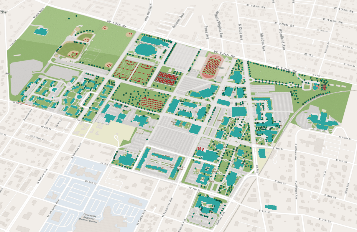
I’m a student at Tennessee Technological University in Cookeville, Tennessee. If you’ve ever heard of it, amazing, and Go Tech! If you haven’t, don’t worry, because we’ll become GIS buddies through this. My long-term goal is to create a 3D rendering of the university’s campus, but the data must first be displayed properly. This is what will be covered below.
In this blog, I will demonstrate how to properly move 2D features (points, lines, and polygons) into a 3D scene using the Interpolate Shape (3D Analyst) tool and Generalize (Editing) tool. I’ll provide a walk-through of the process with the project I’m currently working on.

For this project, I’m working with three data sources that I digitized. These data sources were created in ArcGIS Pro, and the data is not z-aware. Points in the scene represent trees, lines are athletic fields, and polygons are building footprints.
To follow along using my workflow, find an area you want to work in and create three different feature layers in a Map scene: one point feature layer, one line feature layer, and a polygon feature layer for building footprints. Generate a few examples of each on the appropriate layer.
Upload 2D feature classes onto a local scene
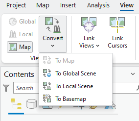
Once satisfied with your content, you can convert your map to a local scene. Select the View tab, click Convert, and select To Local Scene.
A local scene will generate. In the Contents pane, a 3D Layers, 2D Layers, and Elevation Surfaces section will be curated and the existing map feature layers have transferred the scene as well. There is an option to select a global scene. Global scenes have their benefits, such as a spherical, comprehensive presentation of your data for large areas, but I recommend using a local scene for most of your work. The majority of my projects are conducted on a local scene for editing, visualization, and analysis purposes. For more information, see Local and global scenes.
How to assign z-values
You’ll notice that your features may partially or fully disappear with the ground surface. They aren’t invisible or broken. The data isn’t fully appearing because the feature classes are not z-aware with the ground surface. When created in 2D, features will automatically generate x- and y-coordinates, but 3D features also require z-values to indicate their elevation in relation to the ground surface. To assign z-values to the features, we will use the Interpolate Shape (3D Analyst) tool.
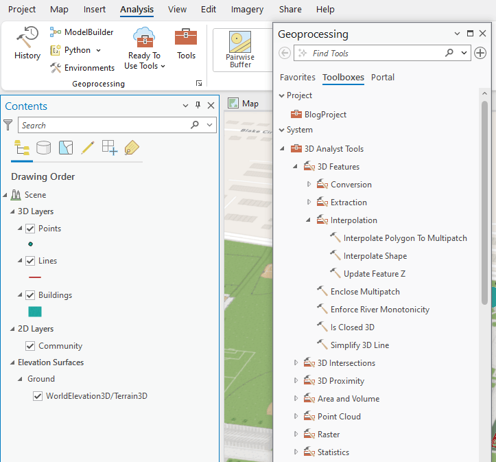
To access the Interpolate Shape tool, select the Analysis tab on the ribbon and click the Tools button to open the Geoprocessing pane. In the Geoprocessing pane, go to the Toolboxes tab, expand the 3D Analyst Tools section, and expand the Interpolation toolbox to access the Interpolate Shape tool. (Alternatively, you can do a quick search using the Find Tools bar.)
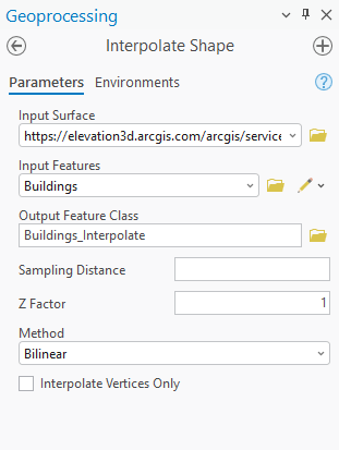
For Input Surface, I used Esri’s WorldElevation3D/Terrain3D ground layer. However, I recommend you download and use a surface file (that is, digital terrain model, digital elevation model) of your area of interest for higher detail and consistency. Esri constantly updates its ground source layer, so the data will change over time.
For Buildings, Lines, and Points Input Features, I typed Buildings_Interpolate, Lines_Interpolate, and Points_Interpolate as the Output Feature Class names to reduce confusion between the newly generated layers and the original not z-aware features.
The remaining parameters were left as their default settings.
This process will be repeated for each feature class and create a feature layer that includes the z-values based on the selected input surface to make them z-aware.
Elevation settings
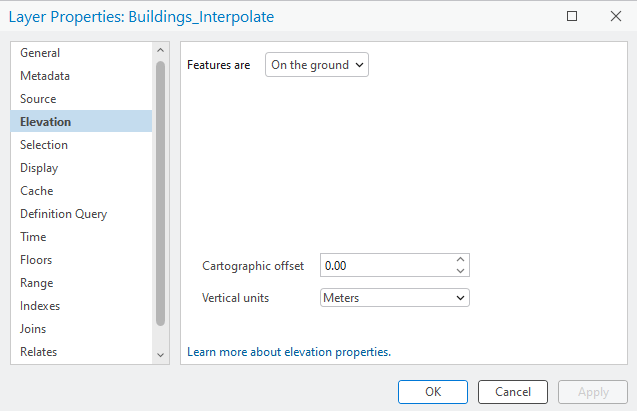
Although the new features are z-aware, some layers may not properly display on the local scene. If this occurs, here’s a quick fix: Right-click the feature and go to Properties of your feature layer and select the Elevation tab. For Features are, confirm the features are on the ground, or adjust if needed, and select On the ground. Click OK and the feature should appear on the local scene surface.
3D deformations from too many vertices
Due to the Interpolate Shape tool creating multiple z-aware vertices along the polygon perimeter, our features now display smoothly to the chosen ground surface. However, this can be an issue for features mapped in areas of elevation change. To view a feature’s vertices, go to the Edit tab on the ribbon, click Edit Vertices in the Tools section, and select an object on the scene.
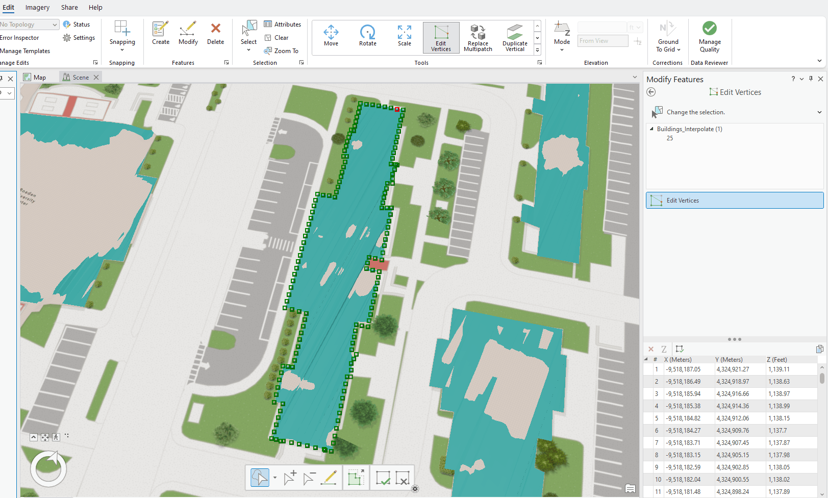
As we can see, the building above has a large amount of vertices across various elevation heights, causing angular surfaces to appear on the polygon. This isn’t always the case with flatter surfaces. If this is an issue, reducing or generalizing the number of vertices of the polygons can resolve the issue. This process can be performed using the Generalize (Editing) tool.
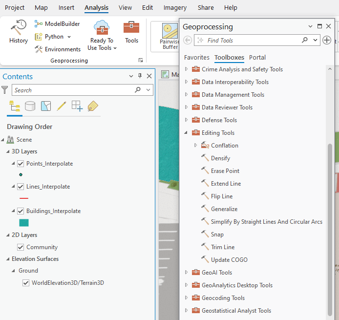
To access the Generalize tool, go to the Toolboxes tab, select the Analysis tab on the ribbon and click the Tools button to open the Geoprocessing pane. In the Geoprocessing pane, expand the Editing Tools section to access the Generalize tool. (Alternatively, you can do a quick search using the Find Tools bar.)
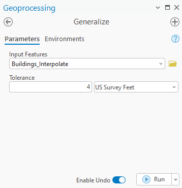
This tool can be run for selected objects or an entire feature. I want to generalize all my features and edit the Tolerance to be 4 US Survey Feet. This value was found through trial and error, so I recommend activating the Enable Undo option at the bottom of the Geoprocessing pane. Repeat this process until you find a tolerance that works toward your desired outcome. Tolerance is optional, but the value and unit will determine the degree of simplification; the larger the tolerance, the more generalized the vertices are.
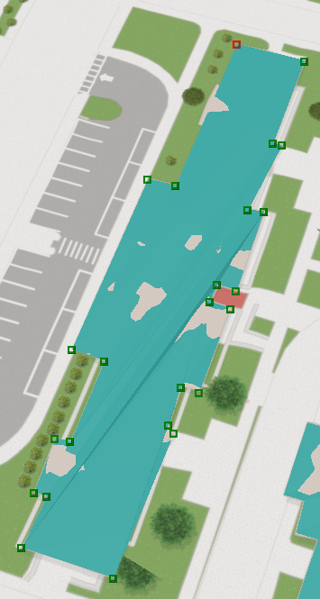
Once run, the vertices for the buildings have been simplified to the corners instead of across the entire perimeter and leveled the polygons.
And voila! You should now have your 2D feature classes displayed on your 3D scene using the Interpolate Shape (3D Analyst) and Generalize (Editing) tool. If you’d like to learn more about 3D mapping, check out the Get Started with 3D Mapping blog. You’re encouraged to provide feedback about this article, including whether you would like more 3D walk-throughs. If you have any questions, see 3D Analyst FAQs.
Licensing information
ArcGIS Pro Basic, Standard, or Advanced: Requires 3D Analyst extension

Article Discussion: