Adding Autodesk Revit files to your GIS scenes provides a view of the built and natural environment. To use Autodesk Revit files as part of my GIS content, my first step is to position, or geolocate, the Autodesk Revit model to a real-world location.
Geolocating in ArcGIS Pro consists of two steps:
- Before adding to my Local scene, assign a coordinate system in ArcGIS Pro
- Adjust the position of the model, if needed
How I accomplish these steps depends on the model and how much I know about that model.
Step 1: Assign the Coordinate System
Before I add this model to a scene, I’ll need to select a coordinate system to use. To select the correct coordinate system, the first question I ask is:
Does this Revit model include location information? There are techniques in Revit to include N/S, E/W, and elevation. This information is stored with the Revit base point. If I can, I’ll ask the author if this information is included, and if so which coordinate system was used for the base point coordinates.
In most cases, I don’t have a way to ask the author about the coordinate system, so I need to make a logical guess. Two important questions:
- Can I make a reasonable guess whether this model is using metric or imperial units?
- Do I know roughly where in the world this model is?
From those two pieces of information, I can make a logical guess of a valid coordinate system to use. If I guess incorrectly, I can refine my choices later. If the model is in the United States, I’ll usually try a State Plane coordinate system that matches my expected units. In other places in the world, a UTM.
To assign my chosen coordinate system, I’ll use the Define Projection geoprocessing tool before adding to the map. The Define Projection tool can be found on the Analysis tab in the Geoprocessing group.
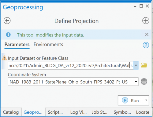
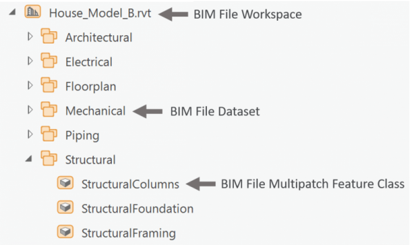
Tip: For the input dataset, pick any of the feature classes inside the BIM File Workspace. In this example, I’ve chosen Walls.
Once the tool is run, the coordinate system is applied to the BIM File Workspace and saved with the file for future use.
Note: A vertical coordinate system is not defined for BIM data. If the vertical coordinate system is unknown, ArcGIS clients assume that the x-, y-, and z-units are identical. For example, if you use DHDN 3-Degree Gauss Zone 1 with meters as linear units, the assumption is that all z-values are also in meters.
Step 2: Adjust the Position (if needed)
Now that my coordinate system is set, I’ll test the position in a new local scene.
For my test, I add a single feature class to a new local scene, usually the Floors or the Walls within the Architectural dataset. If needed, I’ll add a reference layer from my existing GIS content.
Do my Units match?
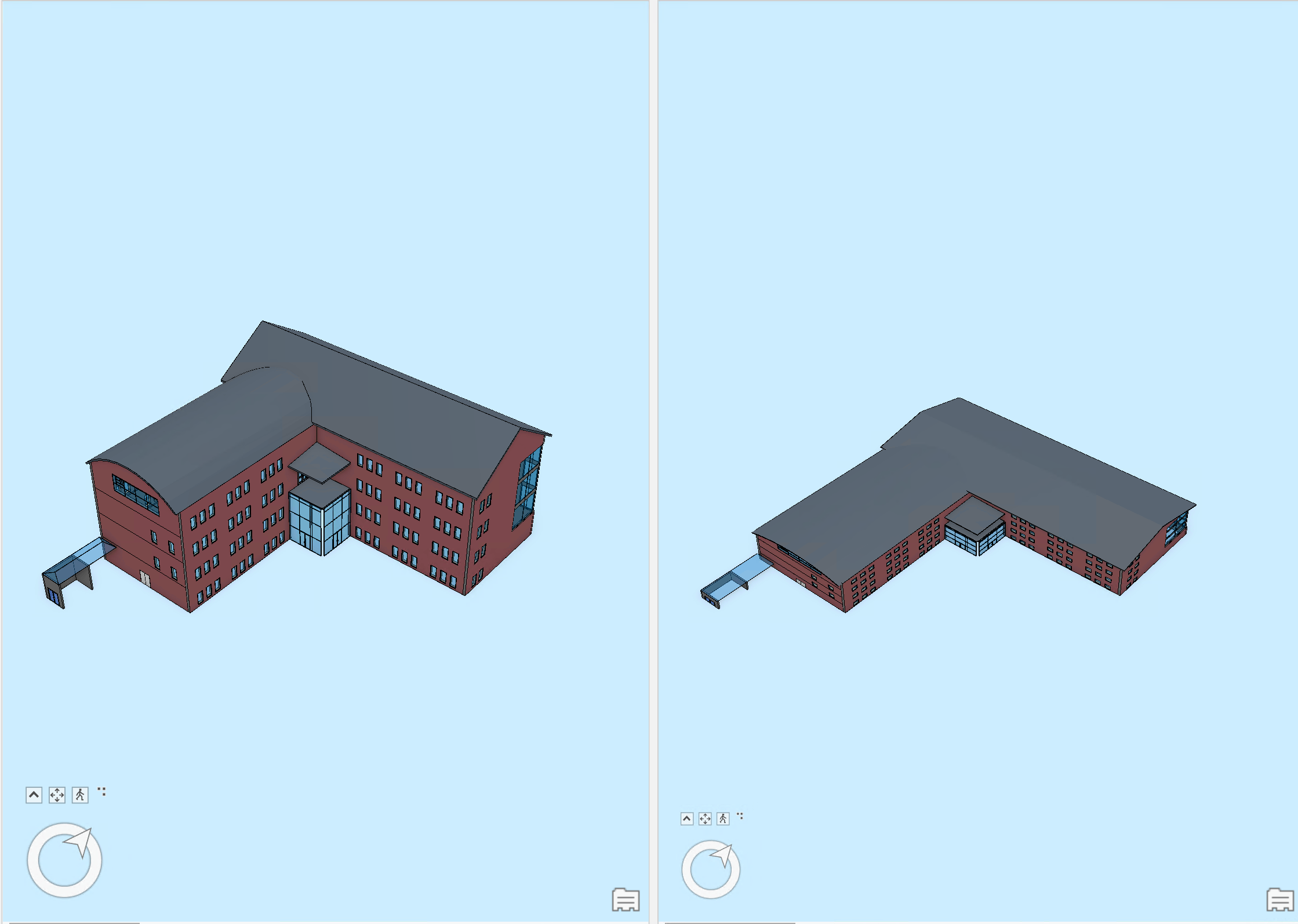
I visually determine whether the coordinate system units match my model. If my model looks stretched, it is likely that the original unit was meters but the currently defined projection is in feet causing the z-values of each feature to be three times longer. If I guessed wrong, I’ll define the projection again and choose a projection with a different unit.
Evaluate Position
If I’ve chosen a correct coordinate system and my Revit model included positioning information in the base point, then my model should be correctly positioned in my scene. Congratulations! We’re done.
If the model is still not positioned correctly, the geographic location is likely not included in the base point. In this case, the data must be georeferenced. In georeferencing, the transform information is saved in a WLD3 file for future uses of this model. Georeferencing is labor intensive, but it only needs to happen once.
Georeference (if Needed)
Tip: Make sure that snapping is on and set to vertex.
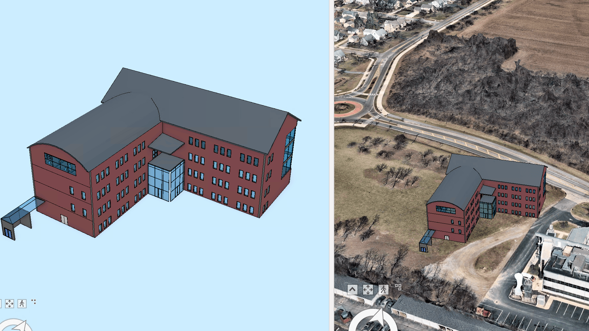
Here’s an example of how I georeferenced a Revit file representing a building on the campus of The Ohio State University. (Thank you to The Ohio State University Facilities Information Technology Services Team for sharing their BIM Data and Nearmap for the Mesh Data.)
My test scene contains just one or two layers from my Revit model. Having only one or two layers in the scene makes the georeferencing process easier. It is easier for me to understand how the layer or layers interact with the surrounding area, especially the location of the structure in relation to the terrain.
Follow along with the steps or watch me work through the process in the video linked below.
1. Set a bookmark to the correct location. In my test scene, navigate to the location where the model should be. While I could just zoom and pan to the correct location, I like to either add some reference feature classes that surround my model or I use the Locate tool in the Inquiry group to zoom to an address. Create a bookmark for this location (area of interest).
2. Open the Georeferencing Tab. In the contents pane, I select the Walls feature layer I added to my scene. The context ribbon for the building appears.

3. Move to Display
Select the bookmark I set previously to center my view on the correct location. Choose the Move to Display button on the Georeference Group to move my building to the general area.
With the move tool active, you can relocate the anchor point by pressing and holding the Ctrl key. The icon changes to an orange cone, which you can reposition anywhere on the structure.
The anchor point can help me position more precisely by snapping to any other reference layers I’ve included in my scene such as ground control points or the corners of known buildings.
4. Fine tuning the position
Now that the layer is in the approximate vicinity, I’ll work with moving, rotating and elevating my model using the tools on the georeference group. I always use the Save whenever switching between tools.
If you need to move the feature in only one direction, hover over the specific arrow handle to be selected and drag the handle to the new position. If the feature needs to be elevated or dropped, hover over the green arrow representing Z and start moving the building in the Z direction needed (up or down).
With snapping enabled, I can position more precisely to any reference layers I’ve included in my scene.
By default, the anchor point is set at the (0,0) of the model. You can relocate the anchor point by pressing and holding the Ctrl key. The icon changes to an orange cone, which you can reposition anywhere on the structure.
If you know the exact angle of rotation, you can use the input window: Press the A and Enter the degrees.
The rotation is always on the horizontal plane.
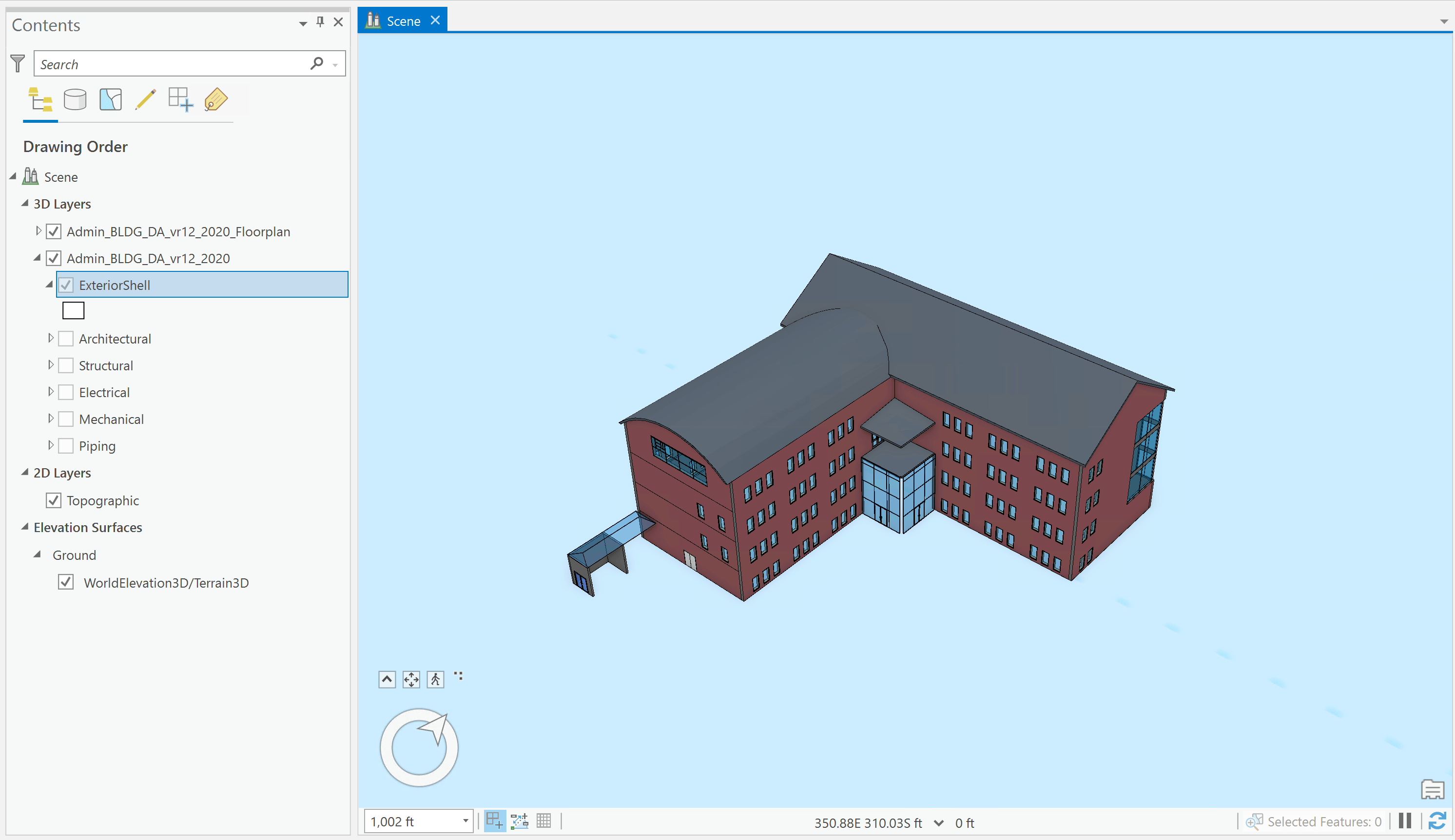
My Revit model is ready to be used in scenes and maps in ArcGIS Pro. I can remove these test layers and add the whole model to my scene. With this building layer, I can visually inspect the various disciplines or floors. I can add more data to interactively analyze the building in the context of its environment. I can share my Building Layer, in addition to other GIS content, as a web scene layer.
Watch me go through these georeferencing steps in this video

Article Discussion: