After a recent post we received quite a few inquiries as to how cross sections are created for visualization in ArcGIS Explorer desktop, and we’ll go through the steps here.
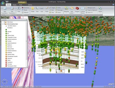
The screen capture above is displaying seismic and geologic profiles (along with wells and well traces) as cross sections in 3D space. In the steps below we will use a photo of Mount St. Helens from it’s May 18th, 1980, eruption and visualize it as a 3D cross section in ArcGIS Explorer as a layer package. The techniques are the same for subsurface and above the surface visualization. Below is a screenshot of what our end result will look like:
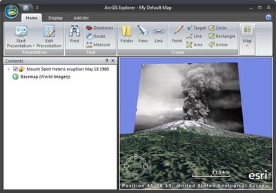
In short, what we want to do is use a raster file or photo (the cross-section we want to display) as a point symbol, and scale and rotate it as needed.
To start we need a point feature to use for the location of the image. You can use an existing point feature or create a new one. One easy way to do this is to create a point note for Mount St. Helens in ArcGIS Explorer and share it as a layer package. Just right click the note on your map, choose share, then save as a layer package.
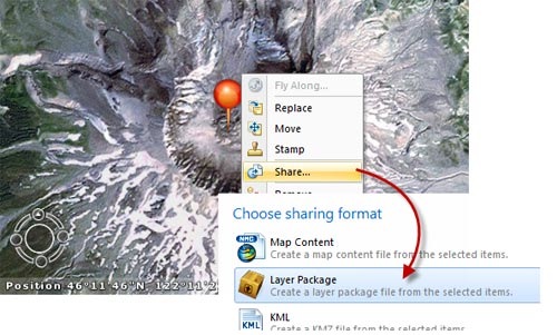
Open the layer package in ArcGlobe. We want to use an image as point symbol. This image will represent the cross section (Mount St. Helens in this example, and the seismic and geologic sections in the earlier example). To use an image as a symbol for the point we need to specifiy and adjust several properties.
In the ArcGlobe table of contents right-click on the layer and choose properties. Click the Globe Display tab, and do the following:
- Check “Scale 3D symbols with distance”
- Uncheck “Rasterize feature layer”
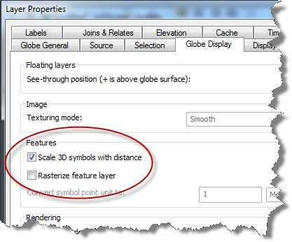
Then click OK and dismiss the dialog. Even though there are more properties to set it is important to click OK when you have modified properties on a tab. ArcGlobe has properties that are only available in certain combinations. If you set properties on one tab and then switch to another tab, a property that you want to set may not be available until the properties from the previous tab are applied. Sometimes this is the case on the same tab. For example, on the Globe Display tab “Scale 3D symbols with distance” is disabled until “Rasterize feature layer” is unchecked and applied. So remember to Apply or OK your changes as you make them.
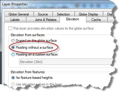
Next, on the Elevation tab specify “Floating without a surface” and click OK.
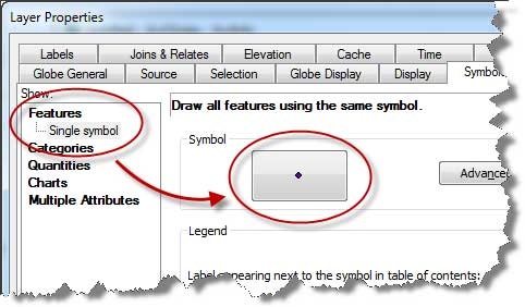
On the layer properties Symbology tab we will specify the type of symbol and the image (ultimately our cross-section) to display as the point symbol. Choose “Single symbol” and click the symbol button.
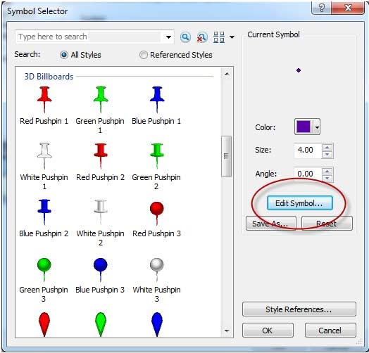
Next, click “Edit Symbol…”
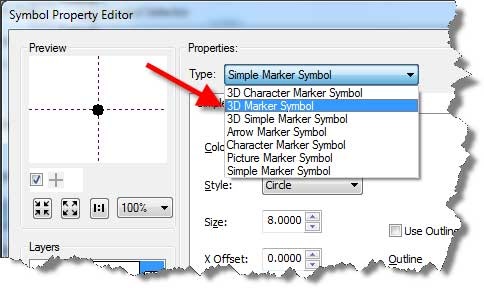
And choose “3D Markersymbol”
Now browse to or copy/paste a URL to the image you want to use as the symbol. For this example I will use this photo from the USGS website:
Click Open and the image loads in for use as a point symbol.
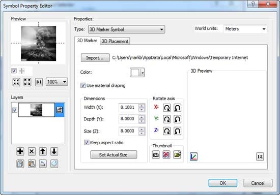
From here, the values you set will depend on the image you have chosen and how it scales in real world space, and some experimentation is necessary.
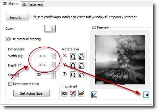
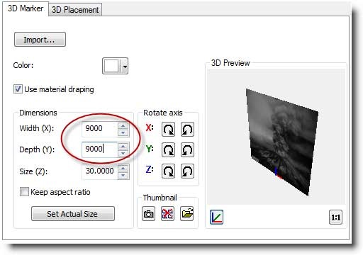
Increase the Size (Z) of the symbol to 30. Also uncheck “Keep aspect ratio.” After doing this it is important that you do not modify the Size (Z) setting again. If you do, you will have to start over and reload the image. Also set the Width (X) and Depth (Y) to equal amounts. We will use 10,000 as our starting point, but will modify those to achieve the desired scaling for this particular photo. Click 1:1 to see the entire image in the 3D Preview as shown below:
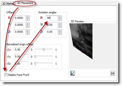
Next click the 3D placement tab and uncheck Display Face Front and set the Rotation angles X value to 90, as shown below:
Click Apply and see what it looks like in your map.
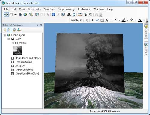
It is pretty close to where we want it to be but still needs some adjustment. The image looks a little bit bigger than the 3D mountain, so let’s fix that first. (Note that the size of the symbol in the table of contents is controlled by the Size (Z) that we originally set before un-checking Keep Aspect Ratio.)
Back at the size settings, I’ll size it to 9000 and see how that looks.
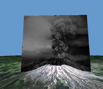
The scale of the image looks a little better now. Next I will slide the image down so the rim of the volcano in the image matches the 3D terrain. To do this, use layer properties and the Elevation tab and set the Layer offset to a lower value. In this case I will use -800.
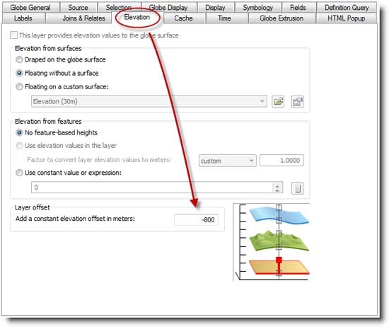
After that adjustment the volcano rims are lining up better. But the horizontal alignment still looks to be a bit off. To correct that I’ll adjust the X offset. Here I have set it higher than it need be to -90 so we can get a better Idea for what this property does:
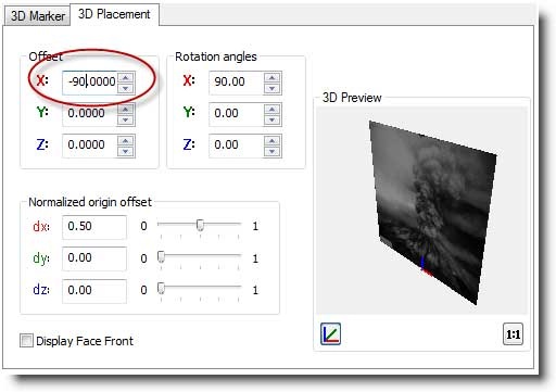
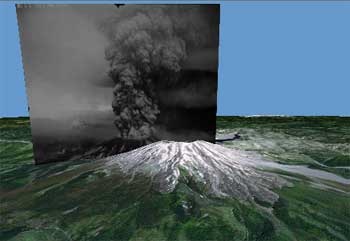
With a little more experimentation we find that a value of -18 looks pretty good.
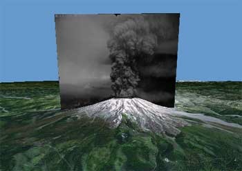
We’re satisfied with how things scale and align now, but one more thing we can do to make the image look better is turn off the layer lighting property.
We’re finished, and now ready to create a layer package that we can open in ArcGIS Explorer desktop.
The layer package created above can be found on ArcGIS Online and you can also view a couple of videos on the Esri Facebook site that show what the layer package looks like in use:
-
Video 1 – a 360-degree tour of the cross section.
-
Video 2 – this one shows how you can view the lower edge of the photo through the surface. To navigate below the surface make sure to check Surface Avoidance off under ArcGIS Explorer Options > Flight Characteristics.
(Submitted by Mark Bockenhauer, ArcGIS Explorer program manager and lead product engineer)

Commenting is not enabled for this article.