Unique value and class breaks renderers allow you to specify a criterion to uniquely symbolize data so the viewer can understand trends and patterns within the data. There are situations where a dataset has a lot of unique values or classes. An example is a utility network dataset. For such datasets, it may not make sense to render data at all scales. To do so, one option is to set a minimum and a maximum scale on the layer. Although with this option, the entire layer will either be shown or hidden, depending on map’s scale. Another option is to use multiple layers that reference the same data. For the correct symbology to display at the correct scale, each layer must be configured to have its own visible scale range, symbology definition, and definition expression defining the subset of data to be made visible at different scales.
These are valid options, but not the most optimal solutions as they require having to manage multiple layers representing the same dataset and are less effective in understanding trends and patterns in the data.
An ideal workflow is to use a single layer that continues to display at all scales and its features or elements switch visibility at different map scales.
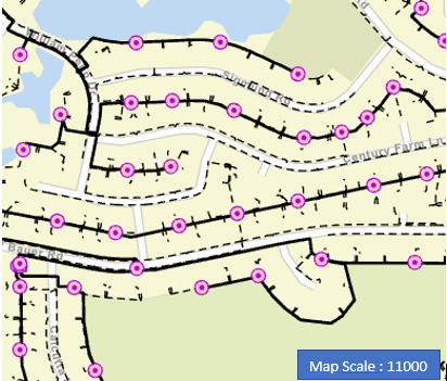
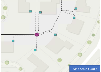
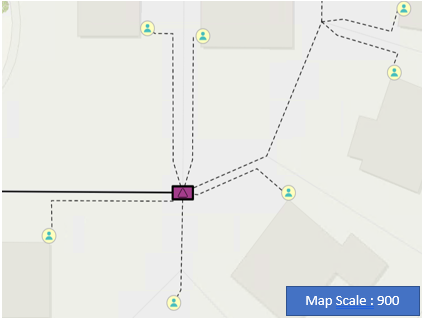
At ArcGIS Runtime 100.12, ArcGIS Runtime SDKs introduced support for rendering scale-based symbol classes and alternate symbols in the mobile map package, published from ArcGIS Pro 2.9. Let’s look at a mobile map package published with ArcGIS Pro 2.9 rendered in an ArcGIS Runtime SDK application. In the map images below, the Electric Device Component layer is configured with scale-based symbols and alternate symbols. Based on the configuration, visibility and symbolization of elements change at different map scales.
In Figure 1 below, Service point and Transformer features are not visible at map scale 11000.
In Figure 2 map scale is 2500 and Service points are displayed with green squares ![]() and Transformers with purple circle around a triangle
and Transformers with purple circle around a triangle ![]() .
.
In Figure 3, as the map’s active scale progresses to 900, symbols switch to the configured alternate symbols. Service points are now drawn using a person icon ![]() and Transformers are represented with a purple rectangle around a triangle
and Transformers are represented with a purple rectangle around a triangle  .
.
Scale-based symbols configuration in ArcGIS Pro
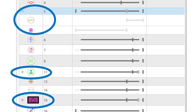
To better understand scale-based symbology, let’s dive into how the Electric Component Device layer’s symbology is configured in ArcGIS Pro. In Figure 4 below, the Symbology pane UI from ArcGIS Pro is illustrating UniqueValueRenderer symbol classes for the Electric Device Component layer. The position of the slider determines the scales at which unique values are visible and can be adjusted to change the visibility range. As seen in the UI, most of the unique values are configured to render at much higher scales (smaller, more zoomed-in areas).
Alternate symbols configuration in ArcGIS Pro
In addition to controlling the visible scale range of each symbol class, display of the data can be further refined by assigning additional symbols to each unique value. In figure 4 above, notice symbols for Fuses (5), Service points (11), and Transformers (15). For these classes, there is more than one symbol defined, denoted by a minus sign if the group is expanded or a plus sign next to the symbol (see circled sections in the image above). These symbols are referred to as alternate symbols.
One of the most common approaches to alternate symbols is to use a complex symbol at large scales (when zoomed into a smaller area) and a simple but related alternate symbol at small scales (when zoomed out to a large area). In the ArcGIS Pro UI above, fuse symbol (5) has a visible scale range of 0–10000 with the pink circle symbol  as its primary symbol. Beyond the 10000 mark, the pink circle
  symbol is replaced by an electric fuse symbol
  . For more information on scale-based symbol classes and alternate symbols, view the ArcGIS Pro documentation.
Now that we have reviewed the conceptual side of scale-based symbols, let’s move on to the API side of things.
ArcGIS Runtime APIs to define scale-based and alternate symbol classes
With ArcGIS Runtime 100.13, developers can now control the visibility and symbology for features according to the scale at which they are displayed by defining scale-based and alternate symbols for unique values and class breaks. Note – that only multilayer symbols are supported as scale-based and alternate symbols. Simple symbols do not qualify for scale-based symbols. In this post, I will walk you through the step-by-step process for defining scale-based symbols for a unique value renderer. For ease of understanding, I will use an ArcGIS Pro UI (in Figure 4 above) as a guideline to define scale-based symbol classes via API.
Step 1) Create or provision multilayer symbols.
The first step is to gather multilayer symbols for unique values. There are two approaches for creating or defining multilayer symbols. Either create them in code using APIs or create symbols in ArcGIS Pro and package them in a mobile style file (.stylx) or as a web style. For this walkthrough, I will use symbols from a style file called Electric_Assets.stylx.
SymbolStyle APIs provide methods to open and query a style file and get access to the symbols and information in style file. A SymbolStyle object holds information about every symbol in the style file. To open a style file, use the OpenAsync method, passing the path to a style file on disk as parameter. For webstyles pass in uri of the published webstyle.

Step 2) Define unique values for the renderer.
Now that we have access to a style file containing symbols, we will create three unique values covering three different scenarios.
Unique value 1: The circuit breaker (4) symbol class is scale-based and has no alternate symbols.
Unique value 2: The fuse (5) symbol class is not scale-based but uses alternate symbols.
Unique value 3: The service point (11) symbol class is scale-based and has alternate symbols.
Unique value 1: Circuit breaker
In the ArcGIS Pro screen capture below, the slider ticks positions for Circuit Breaker (4)  symbol class indicate that the symbol has a visibility scale range. In this case it is 24000 – 0.

First, fetch the circuit breaker multilayer symbol ![]() from style file using the GetSymbolAsync method. GetSymbolAsync takes a set of keys as a parameter and returns the symbol matching the keys passed.
from style file using the GetSymbolAsync method. GetSymbolAsync takes a set of keys as a parameter and returns the symbol matching the keys passed.

Next, set the ReferenceProperties property on the symbol to define the visible scale range for the circuit breaker ![]() symbol class.
symbol class.
SymbolReferenceProperties contains conditional properties that are not directly used by the symbol but rather by the renderer to change how a symbol is visualized based on the state of the map and the data. The constructor for this class takes two parameters: minScale and maxScale. Values passed to these parameters determine visibility of a symbol at a certain scale. A value of 0 for min or max scale represents infinite scale.
In the code below, the Circuit breaker symbol’s reference properties are to set minScale:24000 and maxScale:0. This implies the symbol will display when the map scale is equal to or less than 24000. Then create a unique value object representing circuit breaker.

Unique value 2: Fuse
In ArcGIS Pro’s symbol configuration UI shown below, the Fuse unique value is configured to render at all scales. Its primary symbol, pink circle![]() , switches to an alternate symbol, electric fuse
, switches to an alternate symbol, electric fuse  , when the map scale progresses beyond 10000.

Let’s see some code to set up unique value with similar configuration.
First, get the pink circle ![]() symbol from style file. This will be the primary symbol for the fuse unique value.
symbol from style file. This will be the primary symbol for the fuse unique value.

Since primary symbol, pink circle ![]() , switches to an electric fuse
, switches to an electric fuse ![]() symbol, we need to fetch electric fuse
symbol, we need to fetch electric fuse ![]() symbol from the style file as well.
symbol from the style file as well.

Define the visible scale range for electric fuse multilayer symbol between minScale:10000 and maxScale:0 by setting its ReferenceProperties property. When the map scale is less than or equal to 10000, pink circle
  will switch to this electric fuse symbol
  .
.

This electric fuse  symbol is an alternate symbol for the Fuse unique value. To define alternate symbols for a unique value, create an AlternateSymbols collection, which is essentially a list of multilayer symbols. In this example, we only have one alternate symbol in the list.

Construct a unique value object for the fuse symbol class. In ArcGIS Runtime 100.13, to support alternate symbols for a unique value, a new constructor is introduced on UniqueValue. In addition to other parameters, it takes a collection of multilayer symbols representing alternate symbols.

In the code above, unique value fuse with value 5 is being configured to render at all scales. The primary symbol for the class is pink circle ![]() . As map scale progresses beyond 10000, symbol changes from pink circle
. As map scale progresses beyond 10000, symbol changes from pink circle ![]() to the electric fuse symbol
to the electric fuse symbol  .
.
Unique value 3: Service point
Refer to the Service point (11) symbol class in the ArcGIS Pro UI below. The position of slider ticks indicates that the primary symbol, green square symbol ![]() , is scale-based. The visible scale range for this unique value is 5000–0. Service points are only visible when the map scale is less than or equal to 5000.
, is scale-based. The visible scale range for this unique value is 5000–0. Service points are only visible when the map scale is less than or equal to 5000.
There is also an alternate symbol, a green person ![]() , defined for this class with visible scale range of 1000-0. The primary symbol, green square symbol
, defined for this class with visible scale range of 1000-0. The primary symbol, green square symbol ![]() , is replaced with green person
, is replaced with green person![]() alternate symbol when the map scale progresses beyond 1000.
alternate symbol when the map scale progresses beyond 1000.

Let’s write code to define the third unique value: Service point
Get the green square  symbol from the style file and set the scale range on the primary symbol, the green square
  , via its ReferenceProperties property. The visible scale range is set between minScale:5000 and maxScale:0. This symbol class will not draw on the map until the map scale is 5000 or less.

Fetch the person symbol ![]() from the style file for defining an alternate symbol and define its visibility scale range. By doing so, the primary symbol, green square
from the style file for defining an alternate symbol and define its visibility scale range. By doing so, the primary symbol, green square  , will switch to the green person
 ![]() symbol as the map scale progresses to or beyond 1000.
symbol as the map scale progresses to or beyond 1000.

Create a list of multilayer symbols representing alternate symbols for service point unique value. Add the person ![]() multilayer symbol to the AlternateSymbols collection. In this example, there is only one alternate symbol in the list.
multilayer symbol to the AlternateSymbols collection. In this example, there is only one alternate symbol in the list.

Create the unique value object for service point with all the inputs.

After defining all three unique values (circuit breaker, fuse, service point)- create a unique value renderer. Follow through the steps and refer the code snippet below:
- Create a UniqueValueRenderer.
- Assign the field for the renderer. In this case, the field is called “assetgroup”.
- Define a default symbol for the renderer. Note, the default symbol is applied when no match is found for a value.
- Add all three unique values configured to the renderer’s UniqueValues collection.
- The final step is to apply the renderer to the Electric Device Component layer.
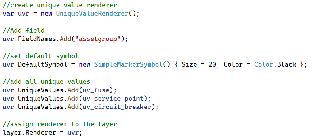
This concludes defining the scaled-based renderer via Runtime APIs. You can follow the same workflow outlined above for unique values to set up ClassBreaksRenderer with scale-based and alternate symbols. To summarize, there are multiple ways to configure scale-based and alternate symbols for a symbol class. In any given scenario, the renderer will pick only one symbol at a given map scale. If the primary symbol’s scale range falls within the map’s current active scale, the primary symbol is used. If not, symbols in the alternate symbols list are iterated through and the first symbol matching the current map scale is picked for rendering. A symbol becomes visible if the map scale is less than or equal to the symbol’s minimum scale and greater than the symbol’s maximum scale. If a symbol class has an invalid scale range, the symbol won’t render for that class.

Article Discussion: