Introduction
A few weeks ago, Esri released Quartz beta’s for all of the ArcGIS Runtime SDKs. If you are an ArcGIS Runtime SDK developer, we hope you have had some time to dive in and investigate the new Quartz features and provide feedback to the development teams. We invite you to continue collaborating with us. So far, we have received a wealth of excellent feedback and great catches, so please keep them coming.
We know that many of you have been waiting anxiously for Quartz’s support for displaying your data using military symbology. The purpose of this blog is to introduce how it all works and to help you get started working with military symbology.
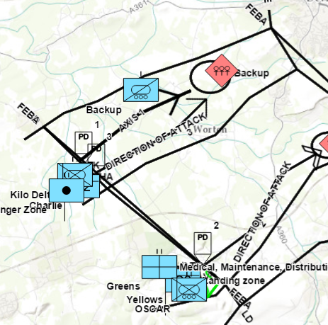
For those of you that used military symbology in pre-Quartz versions of ArcGIS Runtime. Heads up! These concepts now apply to both Graphics and Features. Military symbology can be used for rendering points, lines and polygons in either a GraphicOverlay or a FeatureLayer. This is different from pre-Quartz versions of Runtime, where military symbology could only be displayed as Graphics.
The Symbol Dictionary
Let’s begin by looking at the SymbolDictionary class. A SymbolDictionary makes use of what is known as a *.stylx file. The stylx file contains the symbol primitives for a given symbology specification (such as MIL-STD-2525D), as well as a rule engine that parses input fields from the dictionary. New symbols from the input attributes are assembled based on the attributes of the Feature or Graphic and prepared for rendering. The stylx file is in the form of a binary SQLite database, created from ArcGIS Pro.
The SymbolDictionary constructor takes a given specification, such as “mil2525d”. Each specification depends on attribute names that define the symbology and text of each feature. For example, the MIL-STD-2525D specification looks for attributes named “identity”, “symbolset”, “symbolentity”, and “modifier1”, among many others. These attributes are used to select different symbol primitives in the style file that are assembled to create a unique symbol.
In the current Beta releases for Java and Qt, we provide a pre-built stylx file for you in the SDK. It only contains the specification for MIL-STD-2525D. Other military specs are coming in the Final release, scheduled for November, including MIL-STD-2525B and C. You may be asking yourself, “I wonder if I can create one of these from scratch in Pro, then use it straight away to display my own custom symbology.“. Well, not quite yet, but the long-term plan is to provide this capability, as well as the capability to modify and use existing symbol dictionaries.
The Dictionary Renderer
The companion class to our SymbolDictionary is the DictionaryRenderer. Working together, these two classes make things happen! The DictionaryRenderer class is responsible for the actual visualization of the symbols on the map from the symbol dictionary we just talked about. DictionaryRenderer uses the attributes from the symbol dictionary to display unique multi-layer symbols based on those attributes.
In order to display features using the DictionaryRenderer, you must make sure the DictionaryRenderer and associated SymbolDictionary know which attributes in your data to use. This can be achieved in multiple ways:
- When fields in the FeatureTable and attributes in Graphics have expected names, the DictionaryRenderer automatically finds them. So, author your data so that the attribute names match the attributes needed by the specification. In the case of the MIL-STD-2525D specification, author a feature service (or other data source) with a field named “identity”, another named “symbolset”, and so on. Then in your app, you create a FeatureTable from the source data, create a FeatureLayer from the FeatureTable, and apply the DictionaryRenderer to the FeatureLayer. This causes the symbols to be generated automatically and applied to the layer in the map. A similar workflow applies for Graphics in a GraphicsOverlay. Ideally when creating graphics on the fly, you can give the attributes names that match the specification.
- Use DictionaryRenderer to manually map your attribute names to those expected by the specification. You can map as many attribute names as necessary for the specification, but only need to map attribute names that do not match the specification (all matching attribute names will be automatically matched by the renderer). For example, an expected attribute “symbolset” might appear as the “symbol_set” field in your FeatureTable. In this scenario, you can create a ServiceFeatureTable from a feature service, create a FeatureLayer from that feature table, create a DictionaryRenderer and specifically map the “symbol_set” field name to the “symbolset” name expected by the specification, and finally apply the renderer to the FeatureLayer.
A DictionaryRenderer can be applied to pre-authored data, such as feature services, mobile geodatabases (generated from ArcMap or a sync-enabled feature service), and feature layers in a mobile map package. You can also apply it to a GraphicsOverlay, which allow for on-the-fly graphic generation.
Using the Symbol Dictionary by itself
When used by itself, the SymbolDictionary can be used to find a symbol with provided attributes values by performing a search. This is done by calling findSymbol on the SymbolDictionary, which returns a CIMSymbol. This symbol can then be to create a new Graphic, for example.
You can also use a standalone SymbolDictionary to search for symbol primitives. Symbol primitives are the individual symbols that make up more complex and advanced multilayer military symbols. This is achieved using searchSymbols. You could search for all symbols that have the tag “maritime” in it, for example. The search results contain CIM symbols which you could then either use as they are or extract from them different individual symbols to create a new composite symbol.
Putting it together
Consider the following C++ code:
SymbolDictionary* symbolDictionary =
      new SymbolDictionary("mil2525d", "/some/path/mil2525d.stylx", this);

DictionaryRenderer* renderer = new DictionaryRenderer(symbolDictionary, this);

m_graphicsOverlay->setRenderer(renderer);
The SymbolDictionary is created first, passing in the specification name and the path name to where the .stylx file is located on your device. Next, DictionaryRenderer is created using the symbol dictionary. Now, you have a render that inherits from Renderer, like all the other renderers do in the API, and so you can apply this to your FeatureLayer or, as in this case, your GraphicOverlay.
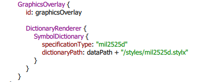
Here is how you do it in QML:
The Quartz Beta samples and API references are the best ways to get fully acquainted with advanced symbology topics like this. You can download the following samples from GitHub:
- Graphics Overlay: Dictionary Renderer
- Graphics Overlay: Dictionary Renderer in 3D Scene
- Search Symbol Dictionary
We hope this was helpful.
Happy coding!


Article Discussion: