GIS integrations into project planning, design, and operations continue to revolutionize the architecture, engineering, and construction (AEC) industry. This includes bridging the gap between designers producing models and drawings in the office with their field counterparts working out on the project site. When used together, tools such as ArcGIS for AutoCAD and ArcGIS Field Maps amplify collaborations across these teams. Both designers and field technicians share needed data with one another from their respective environments.
Understand ArcGIS for AutoCAD
Designers use ArcGIS for AutoCAD to weave GIS into models and CAD drawings, enriching their designs with location and spatial information such as topography, land use, and infrastructure. It allows civil engineers and CAD technicians to access, create, and edit GIS data from design environments without the need to convert data formats. As a plug-in, it also brings GIS capabilities directly into Autodesk design applications such as Autodesk® AutoCAD® and Civil 3D®. ArcGIS for AutoCAD integrates GIS data into the design process, enabling more informed decision-making based on geographical information.
Explore ArcGIS Field Maps
ArcGIS Field Maps combines map viewing and situational awareness, data collection, and location sharing into a unified, mobile-friendly solution. It allows field crews to access project data, capture infrastructure using high accuracy GNSS receivers, collect observations and photos, and complete inspection forms directly from their mobile device. Offline capabilities ensure that field teams can continue their work even in remote areas without internet connectivity. By streamlining data collection and synchronization in real-time, ArcGIS Field Maps enhances field-to-office collaboration and ensures that project data is always current and accurate.
Collaborate across design and field teams
There are many ways to use ArcGIS for AutoCAD and ArcGIS Field Maps together—for example, in streamlining surveying and surface modeling workflows.
The rest of this blog article will focus on just one of the many scenarios in which designers can collaborate with field teams to gather site data and directly inform design decision making, contributing to efficient project delivery. In the scenario below, a civil engineer works together with field crews to capture information relevant to water infrastructure for an in-progress residential development.
Scenario: Water infrastructure design for a residential development
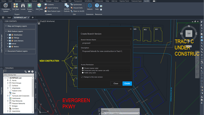
Consider the CAD drawing shown below of an in-progress residential development. You are a designer for the water infrastructure throughout this multi-tract building project. From right to left, Tracts A and B are complete, while residential units located in Tract C are either being designed or are undergoing construction.
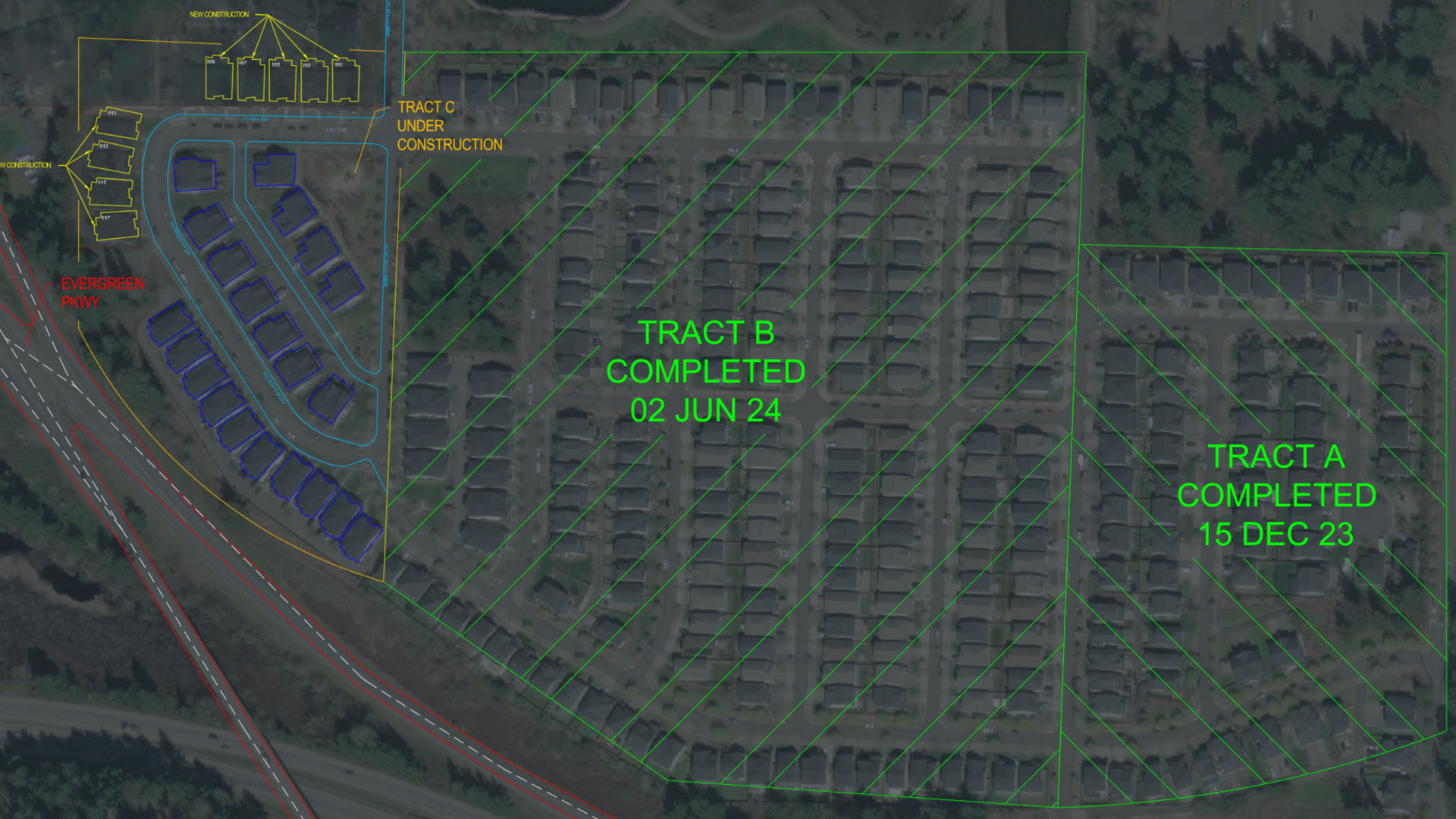
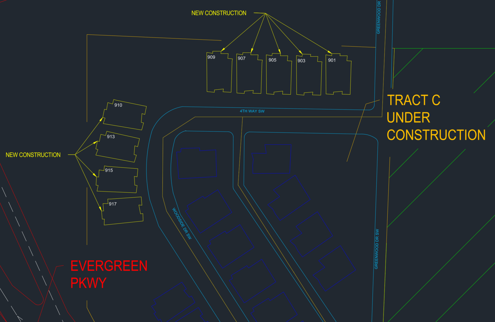
Your current tasks include laying out proposed water infrastructure servicing “new construction” units in Tract C. This includes distribution lines, laterals, fittings, and meters. In addition, you are responsible for deciding on locations for fire hydrants.
Add ArcGIS layers of water infrastructure components to CAD drawings
The water infrastructure, represented as feature layers, is centrally accessed from your organization’s ArcGIS Online (or ArcGIS Enterprise) environment. ArcGIS for AutoCAD allows you to add ArcGIS feature layers to your drawing for editing both attributes and geometry. Synchronize the edits back to the centralized environment for use by other members of the project team.
Using ArcGIS for AutoCAD, you previously made the CAD drawing GIS-ready by assigning a coordinate system and setting the project area. As next steps, you open the Add Data dialog box, sign in using your Esri named user account, and browse your organization’s ArcGIS content. You find the feature layers containing project information for the water infrastructure and add these layers to the drawing.
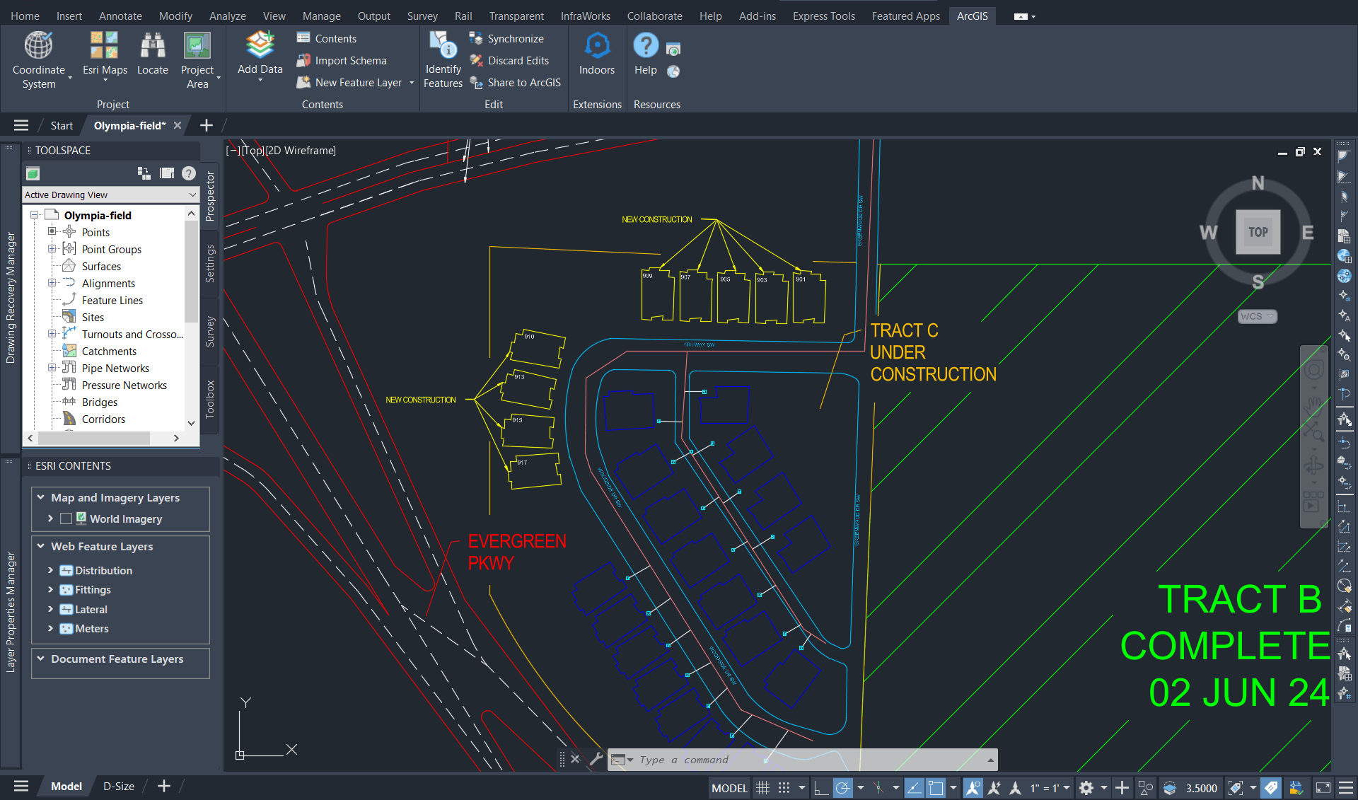
Before starting your normal CAD commands to draw the proposed water infrastructure, you realize that you are lacking information for existing fire hydrants. Without such context, you are reluctant to proceed with laying out the proposed water infrastructure components.
Capture water infrastructure component information from the field
You reach out to the field team, ask them to walk the portion of the site pertaining to the units in design, and document the location and conditions of any existing fire hydrants. Before visiting the project site, the field team creates a form in ArcGIS Field Maps Designer. They associate the newly created form with point features to facilitate capturing of existing fire hydrants. Added within the form are prompts to inform the condition of fire hydrants found on site, such as a switch to indicate True or False for Is Hydrant Corroded?.
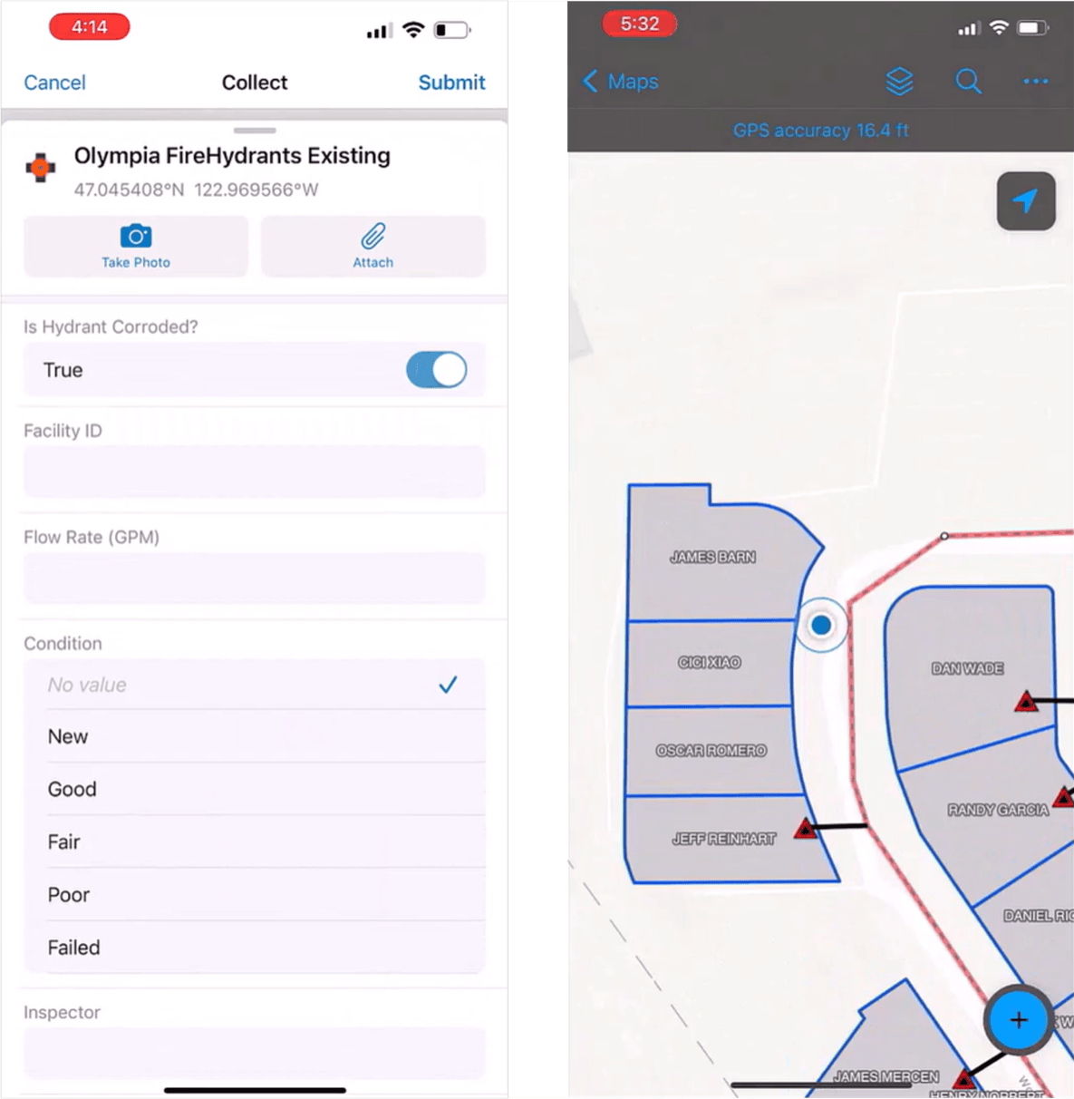
A field technician then visits the project site. Using ArcGIS Field Maps, the field technician opens a map, which displays both the form and the feature layers of the water infrastructure components. While walking the site, the field technician encounters a fire hydrant. They add a point feature to denote the fire hydrant location and fill out the associated form. Additionally, they take a photograph of the fire hydrant and attach it to the point feature. Information for the fire hydrant found on the project site is then synchronized back to your organization’s ArcGIS Online environment. Check out a recap of the workflow so far in the video below.
Take the next design step using field-gathered hydrant information
Returning to your design environment, such as Civil 3D, you synchronize on the feature layer of points representing the fire hydrants so that the information captured in the field is added to the drawing. The newly added layer information includes a geolocated point of the fire hydrant. Also included are the fire hydrant attributes indicating the component condition and the photograph, which were all captured from the field.
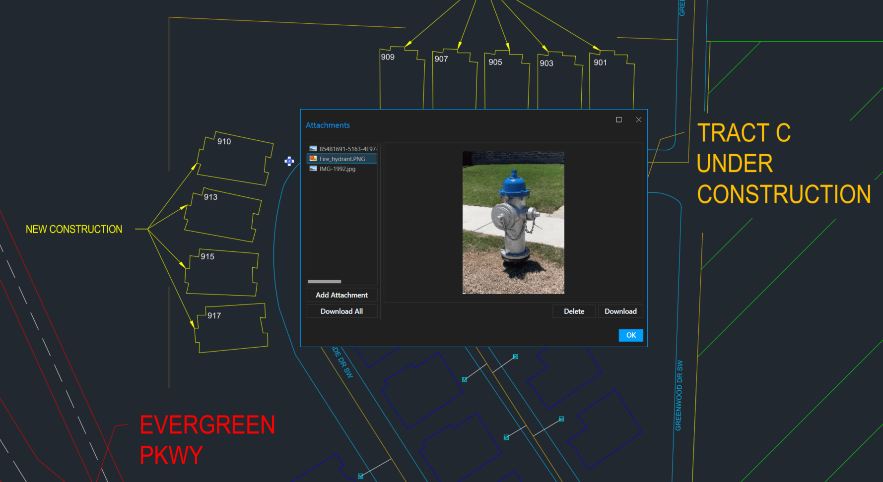
All of this information together can inform your decisions about the placement of other water infrastructure components, such as the laterals and meters servicing each residential unit. You are now equipped to take the next design step in your project, taking into account the added context of the existing fire hydrant’s location and condition.
Summary
Bringing GIS to and from CAD environments, while simplifying data sharing between design and field teams, enables more informed decision-making. Combined use of ArcGIS for AutoCAD and ArcGIS Field Maps uniquely enhances these collaborations, benefitting all aspects of your engineering project workflow. As industries such as AEC, environmental consulting, transportation, and utilities increasingly adopt the geographic approach, integrations between GIS, design, and field technologies will become increasingly pivotal to efficient project delivery.
Download ArcGIS for AutoCAD and get started with ArcGIS Field Maps to bring your design and field teams closer together.


Article Discussion: