In the ArcGIS Pro 2.6 release, there is a new functionality that allows you to create network topology in line and point features, designed to meet the needs of the traditional geometric network community. This functionality is called Trace Network and provides a simple yet comprehensive network solution for non-utility users.
The following are the key pieces of functionality from the trace network that differ from the utility network:
- Flexible schema
- Direct migration from a geometry network
- Trace by Flow Direction
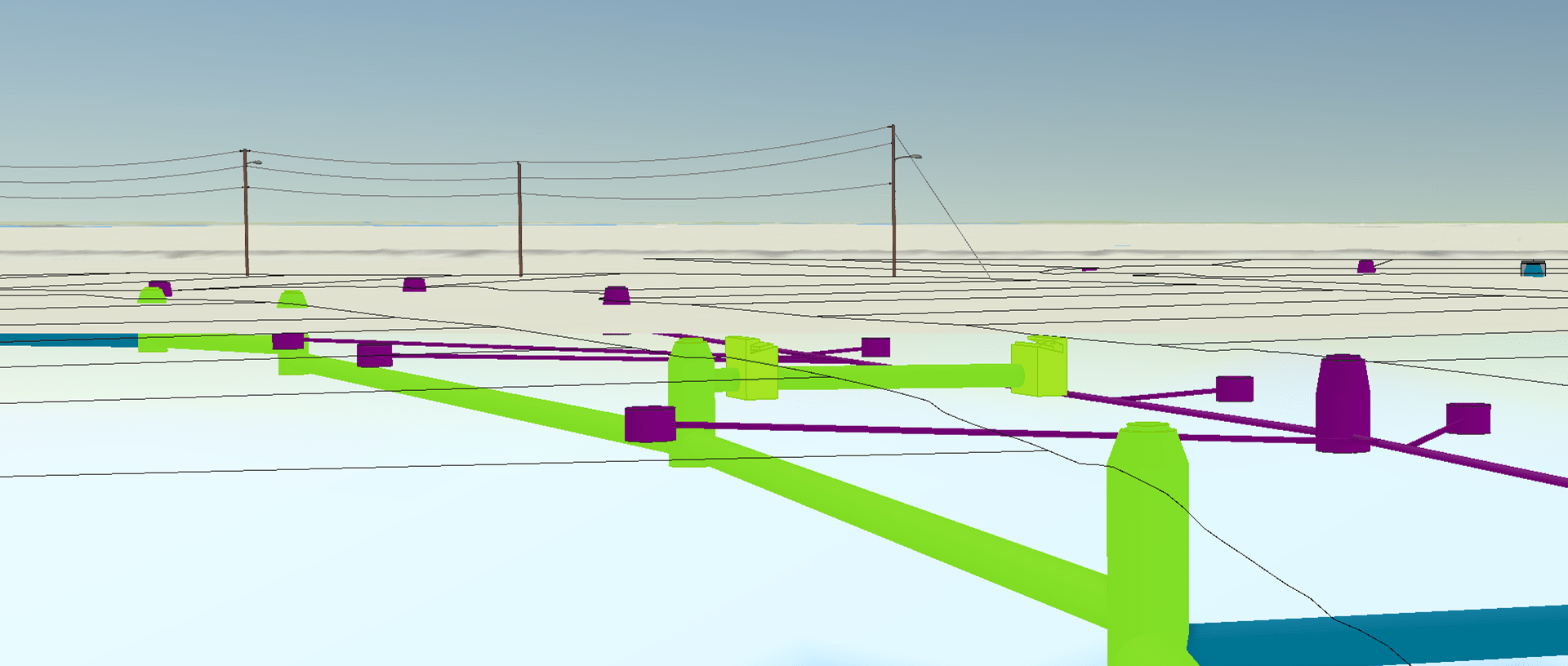
Trace Network extends the capabilities of and adds intelligence to Autodesk Civil 3D Gravity and Pressure Networks, enabling advanced analytic functionality, such as the ability to set flow direction, run a trace on the network, or generate network diagrams once they are incorporated into the geodatabase.
- You can run traces in your networks without having the Utility Model.
- You can run traces in the middle of the design process.
- With the flexible schema, you can use the Civil 3D attributes as filter in the trace.
- You can consolidate networks from different Civil 3D files in one and run traces across them.
In the next section, you can see the steps to add an Autodesk Civil 3D Gravity Network (Pipes and Structures) into a geodatabase, to create a trace network to define a topology on those feature classes and run a trace.
The Utility Network solution may be a better option for facility engineering functions. For example, the Trace Network solution does not represent active devices — such as valves, switches, meters, and pumps — contained features, or structural support elements. In the use case described in this blog, the trace network was used to provide a near real-time model to evaluate directional flow based on the Civil 3d elements.
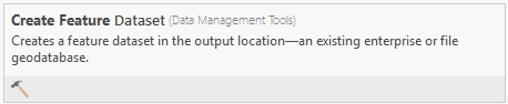
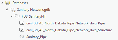
Create Feature Dataset
The first step is to create a feature dataset in your geodatabase. The trace network components and your network feature classes are stored here.
From the Geoprocessing tools pane, click Create Feature Dataset.
In the field Output Geodatabase, select your geodatabase. Define a name in the Feature Dataset Name text box and assign a coordinate system.
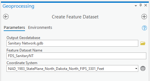
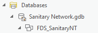
Press Run
Add feature classes to the Geodatabase
Use the following steps to convert the Autodesk Civil 3D feature classes from the Gravity Network to feature classes in the geodatabase.
From the Geoprocessing tools pane, select Feature Class To Geodatabase.
For Input Features, you can select the Feature Layers from the Civil 3D file that were already loaded in the map, or you can navigate to the file and select them from there, as was done in this example.
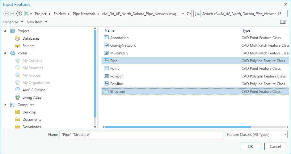
Click Pipe and Structure, and click OK. The feature classes are assigned as input features in the geoprocessing tool.
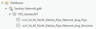
Select the new feature dataset that was created in the previous step in the Output Geodatabase setting.
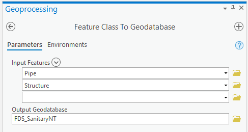
Click Run. The Feature Classes are converted into the Geodatabase.
Create a trace network
Use the following steps to create a trace network for the dataset.
From the Geoprocessing tools pane, click Create Trace Network.
For Input Feature Dataset, select the feature dataset. Then define a name for the new trace network in the Trace Network Name field. Select the structure feature class for the Input Junctions option, select the pipe as the Input Edge option, and set Simple edge as Connectivity Policy.
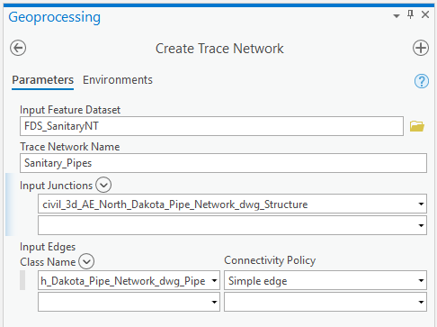
Click Run. The new trace network is created.
Enable and validate the Network Topology
Once the trace network is created, the next step is to enable network topology, which allows you to run different types of traces in your network. After this step is done, validate the network topology, which is necessary every time the topology is created or edited.
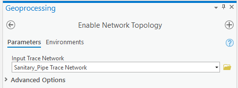
From the Geoprocessing tools pane, click Enable Network Topology.
For Input Trace Network, select the Trace Network created in the previous step. Then click Run to enable it.
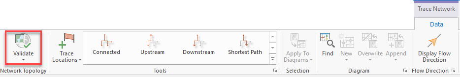
After enabling the network topology, click Validate. This tells you if there is any dirty area that needs to be solved before running a trace.
Run a Trace
After completing all the previous steps, you are ready to run a trace on your network.
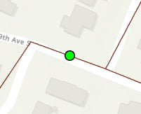
First, you must define a trace location. This is the point where your trace begins.
Click Trace Location.

Select the starting point in a Pipe.
If you need to define a stopping point for your trace, you can place a barrier in the network.
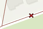
Click Barriers
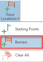
Insert it in a pipe where you want to stop the trace.
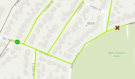
Select the type of trace that you want to run.
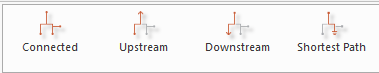
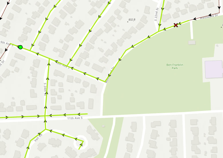
In this case, an upstream trace was run. The trace stopped in the pipe with the barrier.
You can also verify the flow direction and correct it, if necessary. Click Display Flow Direction.

The Flow direction is shown in the map.

Article Discussion: