Public safety organizations rely on reliable, repeatable incident mapping of address-based data. Some agencies have created in-house geocoding using locally developed E911 points and street files. Other agencies subscribe to location-based services that use commercially provided street data. A typical fire/emergency medical service (EMS) provider could respond to 100 to 300 incidents per one thousand residents, which might result in 20,000 incident responses or more in one year.

This total might include multiple responses to the same house, convalescent care facility, or large apartment complex. Since one address may be involved in many responses, it is not necessary to geocode each response record. Instead, street addresses may be summarized, which creates a much smaller address set. By geocoding the summary set, joining longitude and latitude coordinates back to the parent incident table, and creating and saving an XY response dataset, many points can be mapped by geocoding many fewer records. As always, the key to success involves clean, standardized address assignments.
Esri provides several ways to geocode addresses with online services. For several years, ArcGIS Online has included an ArcGIS World Geocoding Service that provides an effective multiple field geocoding service. It includes the ability to edit and re-geocode complex addresses. ArcGIS Pro includes many tools to perform custom and standard ArcGIS Online World Geocoding Service tasks.
Geocoding using the Online World Geocoding Service requires a current ArcGIS Online subscription and uses service credits. Forty credits are needed to geocode 1,000 addresses. A single ArcGIS Online account includes 100 annual service credits. Credits remaining at year’s end do not carry into the following year.
This exercise uses actual response data from the Kent Fire Department in Washington state for two response districts in downtown Kent. It teaches a simplified workflow for posting more than 1,000 incidents to a map in ArcGIS Pro.
The Kent Fire Department has used address geocoding for many years and has applied a current, standard addressing schema. The addressing schema is referenced in National Fire Protection Association Standard 950 Standard for Data Development and Exchange for the Fire Service and is supported by the Federal Geographic Data Committee (FGDC) in FGDC-STD-016-2011, United States Thoroughfare, Landmark, and Postal Address Data Standard. You can read these documents to learn more about addressing standards.
Create a Project in ArcGIS Pro
ArcGIS Pro is web based and requires an ArcGIS Online organization account. To begin, install ArcGIS Pro on your mapping computer and verify that you have an ArcGIS Online license. Log in to ArcGIS Pro. When ArcGIS Pro starts, choose Create a new project using the Map.aptx template. Use \KFD\KFD_AGOL, the same KFD root folder used for the ArcGIS Online exercise, to create a new project folder just under KFD. Name the project and its project folder KFD_Pro.
Add Data and Change the Basemap
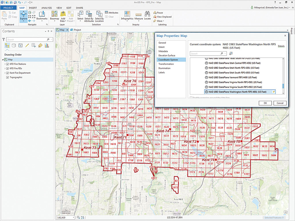
In ArcGIS Pro, inspect the tabs at the top of the workspace that expose ArcGIS Pro functionality.
- Click the MAPS tab and choose Basemap to change the default Topographic basemap to OpenStreetMap.
- Click the Add Data button and navigate to \KFD\KFD_AGOL\.
- Select Data—Add data to the map and select Kent Fire Department.lyr.
- Zoom the map extent to the extent of the Kent Fire Department.lyr.
- Select Data—Add data to the map and select KFD Fire RDs.lyr, and Kent Fire Stations.lyr. Do not load the KFD Incidents layer.
This exercise uses the same reference data as “Optimize Online Geocoding.” Kent Fire Department.lyr showing the fire district boundaries layer, was created in Washington State Plane North American Datum (NAD83) North and will be used to set the coordinate system in future tasks.
In “Optimize Online Geocoding,” the underlying dataset was populated. Near the end of this exercise, the KFD Incidents.lyr will be used to symbolize the incidents. Verify that the data links are valid for all three layers and that you see eight fire stations and a fire district boundary.
Consider Coordinate Systems and Transformations
Change the coordinate system to Washington State Plane NAD 1983 North US Feet.
- Right-click Map (the data frame) in the table of contents (TOC) and choose Properties. Choose Projected coordinate system > State Plane > NAD 1983 (2011) (US Feet) > NAD 1983 (2011) StatePlane Washington North FIPS 4601 (US Feet).
- Select Transformation and verify that Convert from is set to GCS WGS 1984, Into is set to GCS NAD 1983 2011 transformation, and Using is set to WGS 1984 (ITRF00) To NAD 1983 2011.
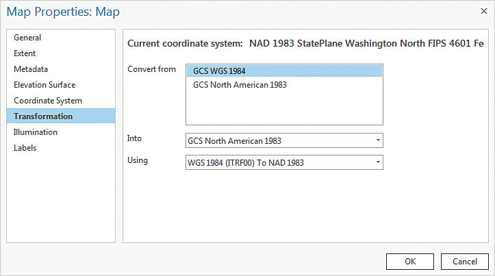
When they were originally defined, the North American Datum 1983 (NAD 1983) and the World Geodetic System 1984 (WGS 1984) were equivalent. To minimize coordinate changes, NAD 1983 is tied to the North American, Pacific (for Hawaii, Guam), and Marianas tectonic plates. WGS 1984 is tied to the International Terrestrial Reference System (ITRF), which is independent of tectonic plates. Over time, the two coordinate systems have become increasingly different. ArcGIS Pro provides a higher-quality transformation that will be used for this exercise. Unless it is changed, the geocoding reference data will be in WGS 1984 geographic coordinates.
Preparing Incident Data for Geocoding
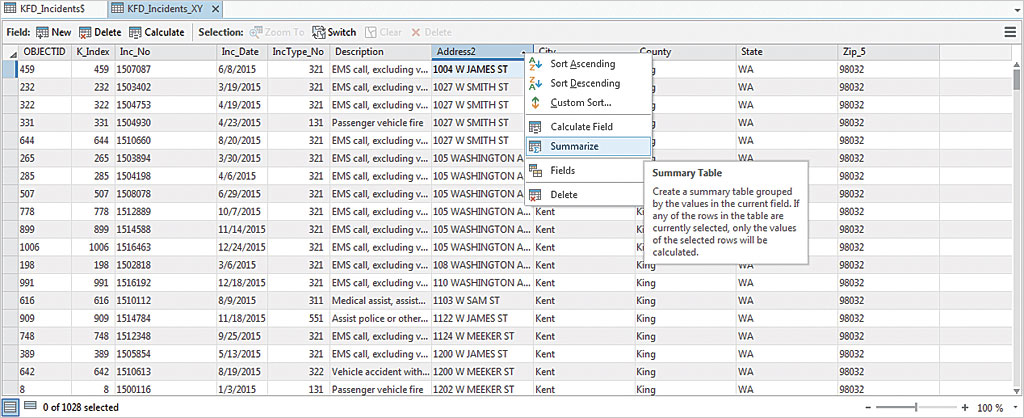
To convert incident data stored in a Microsoft Excel spreadsheet, click Add Data and navigate to KFD_AGOL\XLSFiles\. Open KFD_Incidents.xls, and select KFD_Incidents$. Once added, right-click on it and open this worksheet. Sort the Address2 field in Ascending order to preview duplicate addresses. Many of the 1,028 records reference the same address. These records can be summarized as one geocoding record.
Export Incident Data in Excel to a Geodatabase Table
To protect the original data format before summarizing on the Address2 field, export the worksheet as a geodatabase table.
- With the KFD_Incidents$ table visible, click the menu on the right side of the table (three horizontal bars) and choose Export. Export KFD_Incidents$ to the KFD_Pro file geodatabase as KFD_Incidents_XY. Click Run.
- Open KFD_Incidents_XY and verify that it contains all 1,028 exported records.
- Notice that each duplicate Address2 record contains the same values for City, County, State, and Zip_5. If they did not, additional steps might be required to edit or perform additional rematching steps.
- Remove KFD_Incidents$ from the TOC and save the map.
Summarize Address Field
To summarize all incident addresses, right-click the Address2 field and select Summarize.
- Make sure the Input Table is KFD_Incidents_XY and set Output Table to KFD_Incidents_Address2_Sum_1_XY.
- Under Statistics Fields, select City, County, State, and Zip_5 and use the Statistics Type FIRST.
- Click Run.
Remember, these fields must contain identical content for each unique address string. Save the summary output in KFD_Pro.gdb as KFD_Incidents_Address2_Sum_1_XY. This naming convention references the source table (KFD_Incidents_Address2_Sum1_XY), the summarized field (Address2), and the summary (Sum1). It identifies the dataset as a table only (XY). Although it is long, it is very descriptive.
Open the summary table added to the project and explore the data. Sort Count_Address2 in descending order and preview repeated response addresses. Notice that the summary table contains only 129 unique addresses, compared to the source table, KFD_Incidents_XY, which contains 1,028 responses.
Geocode Addresses
Geocoding the summary addresses, calculating their coordinates, joining coordinates back to the response table, and posting an XY event theme results in a considerable savings immediately. By saving the geocoded coordinates in a reference table, they can be assigned to records in future years so that only new addresses will need to be geocoded.
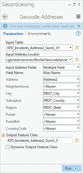
In the TOC, right-click KFD_Incidents_Address2_Sum1_XY and choose Geocode Addresses.
In the Geoprocessing pane in Parameter, make sure the Input Table is KFD_Incidents_Address2_Sum_1_XY.
For Input Address Locators, click the dropdown and select the https://geocode.arcgis.com/arcgis/rest/services/World/ GeocodeServer, the default GeocodeServer XY provider.
A list of standardized field names and aliases will appear. In that list, set the following values:
- Set Address to Address2.
- Skip Neighborhood.
- Set City to FIRST_City.
- Set Subregion to FIRST_County.
- Set Region to FIRST_State.
- Set Postal to FIRST_Zip_5.
- Skip Postal Ext and CountryCode.
- For Output Feature Class, put KFD_Incidents_Address2_Sum1_X, storing them in KFD_Pro.gdb.
- Do not click Run.
The reference geocoding data is stored in WGS 1984, a geographic coordinate system. Although the ArcGIS Pro geocoder will calculate decimal degrees longitude and latitude values for all points, point output to the local State Plane coordinate system can be specified in the Geoprocessing pane; choose Environments.
- In the Output Coordinate System dropdown, select Kent Fire Department.
- Omit Output CONFIG Keyword.
- Click Run to geocode 129 summarized address records.
Review Geocoded Addresses
All records should be matched. If you needed to rematch to fix ties or unmatched records, you would click Yes to start the rematch process button and explore the Interactive Rematch wizard. You would zoom to the first geocoded record and inspect the list of candidate sites. If you approved the first candidate highlighted in cyan, you would do nothing. If you saw a better candidate, you would select it and rematch.
KFD_Incidents_Address2_Sum1_X will be added to the map. Preview geocoding results on the map. All 129 points should map just northwest of Station 71, in or near FD 1516 and FD 1517.
- Right-click on this layer in the TOC and choose Attribute table to open and inspect the KFD_Incident_Addsess2_Sum1_X table.
- Locate longitude and latitude fields (X and Y). These fields contain WGS 84 geographic coordinates that will be joined to the KFD_Incidents_XY table. Remember the position of these fields in the table.
- Clean up the map. Remove the KFD_Incidents_Address2_Sum1_XY table. Close but do not remove the KFD_Incidents_Address2_Sum1_X feature layer. KFD_Incidents_XY should be the only open table. In the next steps, new fields will be added to this table, a tabular join created, and new fields calculated. A simplified project, combining standardized layer and field names, minimizes the chance for error.
Create Longitude, Latitude Fields in Incidents Table
Verify that only the KFD_Incidents_XY table is visible and active. The next steps will create two new fields in KFD_Incidents_XY to store coordinates.
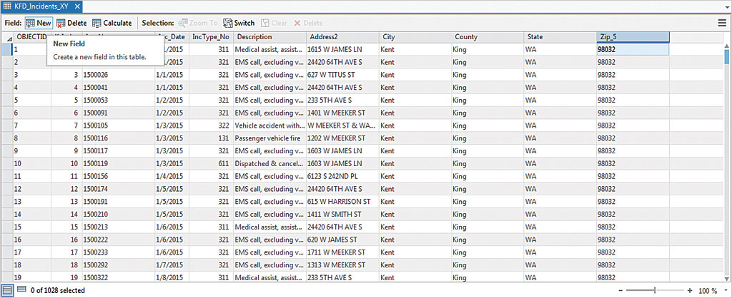
- In the upper left corner of the KFD_Incidents_XY table, click New Field to open the field dialog box.
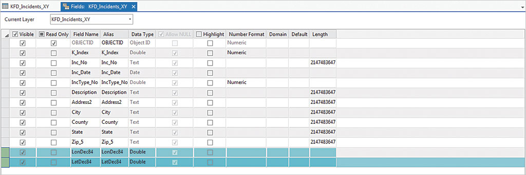
- Go to the last Field Name field (after Zip_5) and enter LonDec84 for Field Name and Alias and set the Data Type to Double.
To see another way to add a field, go to the ribbon and click the FIELDS tab. In the Changes section, click the New Field button and enter LatDec84 for name and alias and set Data Type to Double. When finished, check your work, and click the Save button in the Changes group. In the table area, close the Fields dialog box and note the new fields in the KFD_Incidents_XY table. Save the project.
Join Geocoded Attributes to Incident Table
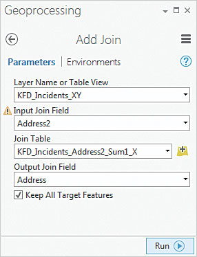
- In the TOC, right-click KFD_Incidents_XY and choose Joins and Relates > Add Join. Complete the Add Join wizard by making the following changes:
- Assign Address2 to Input Join Field.
- Set the Join Table to KFD_Incidents_Address2_Sum_1_X.
- Scroll down the drop-down for Output Join Field and set it to Address (not Address2).
- Check the box for Keep all Target Features.
- Click Run to execute the join. Inspect the joined KFD_Incidents_XY table. Locate the X and Y fields containing longitude and latitude in decimal degrees. Save the project.
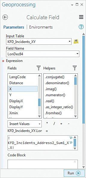
Calculating Coordinates Using Joined Data
Now to populate the LonDec84 and LatDec84 fields with the values in the X and Y fields.
- In the KFD_Incidents_XY table, locate and right-click the LonDec84 field and select Calculate Field.
- In the Calculate Field wizard, confirm the Input Table is KFD_Incidents_XY table and LonDec84 is the Field Name. Scroll down through the Fields list and select X. Double-click X to preview the calculation formula. Leave all other areas with default values and click Run.
- Populate the LatDec84 field in the same way. Right-click the LatDec84 field, choose Calculate Field, select Y as the Field, double-click to preview the formula, and click Run.
Make sure LonDec84 and LatDec84 contain the values from the X and Y fields.
The join is no longer needed, so right-click KFD_Incidents_XY in the TOC and choose Joins and Relates > Remove All Joins. Save the project.
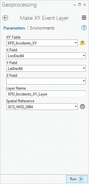
Posting, Symbolizing, and Exporting Incidents
- Right-click the KFD_Incidents_XY table in the TOC and choose Display XY Data to invoke the Make XY Event Layer wizard. Make these changes to the wizard:
- Make sure the XY Table is KFD_Incidents _XY.
- Set the X Field to LonDec84 and Y Field to LatDec84.
- Set the Layer Name to KFD_Incidents_XY_Layer.
- Leave the Z Field blank and leave Spatial Reference as CGS_WGS_1984.
- Click Run to execute the XY Event Layer tool.
The new XY layer will be added to the map. Inspect the points on the map and open its table to verify that it contains 1,028 records. Save the map again.
Export XY Incident Data to a Feature Class
In the KFD_Incidents_XY_Layer attribute table, verify that no event layer records are selected and note the IncType_No field. Although this field supports symbology in the KFD Incidents.lyr file, symbolize Incident and Address2 summary points to confirm that all points have mapped properly.
- In the TOC, right-click KFD_Incidents_Address2_Sum1_X and choose Symbology. In the Symbology wizard, click the symbol and select the red Circle 3 symbol.
- Next open the symbology for KFD_Incidents_XY_Layer and select the black Cross 1 symbol. Explore the map and verify that all incident points align with Address2 summary points.
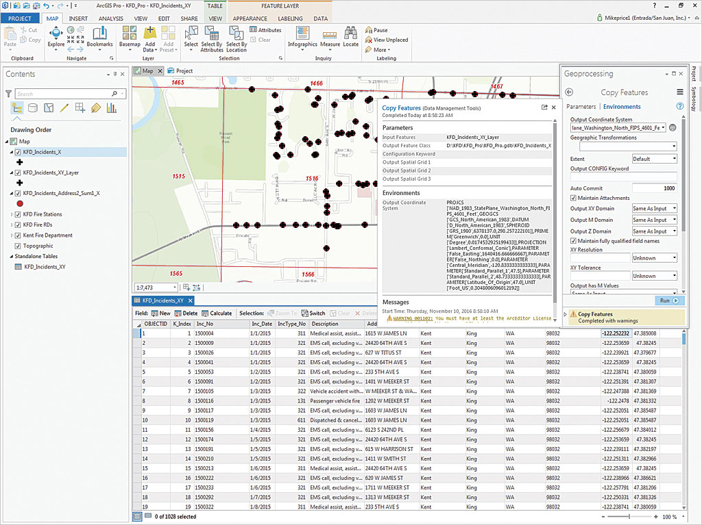
- In the TOC, right-click KFD_Incidents_XY_Layer and choose Data > Export Features. In the Copy Features Parameters dialog box, keep KFD_Incidents_XY_Layer as Input Features and set Output Feature Class to KFD_Incidents_X in KFD_Pro.gdb.
- Click Environments in the Geoprocessing pane. Use the Kent Fire Department feature class to set the Output Coordinate System to NAD 1983 (2011) StatePlane Washington North FIPS 4601 (US Feet).
- Accept all other defaults and click Run. Turn off the other Incident layers and inspect the KFD_Incidents_X (exported points). Click the Copy Features dialog box and click the yellow warning triangle to read the message. Save the map again.
Mapping Incidents by NFIRS Type
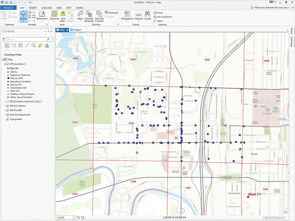
To use the National Fire Incident Reporting System (NFIRS) coding to symbolize the incident types, import layer symbology.
- In the TOC, right-click KFD_Incidents_X and select Symbology.
- In the Symbology pane, click the three horizontal bars on the right side and choose Import symbology.
- For Symbology Layer, click the folder icon and navigate to KFD_Incidents.lyr in KFD_AGOL\GDBFiles\WASP83NF and select it.
- Set Type to VALUE_FIELD with both Source and Target Fields set to IncType_No. Click Run to execute and inspect the mapped symbology.
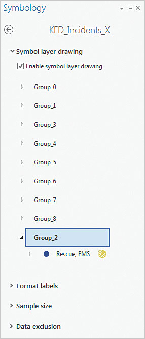
- Many incident types are Rescue, EMS. To move the large blue Rescue, EMS symbols to the bottom of a stacked set, right-click KFD_Incidents_X and select symbology again.
- Click the three bars at the top of the pane and select Advanced.
- Expand Symbol layer drawing, check the Enable symbol layer drawing box, and Move Group_2 (containing Rescue, EMS incidents) to the bottom of the stack.
- Close Symbology and any open tables and save the project.
Summary
This ArcGIS Pro exercise required geocoding only 129 unique address records to map 1,028 incidents because incidents that were at the same address were summarized. Consequently, only four ArcGIS Online credits were consumed. Before you geocode, remember to standardize addresses so you can efficiently summarize them.
Acknowledgments
Special thanks again go to the Kent Fire Department and the Kent Regional Fire Authority for the opportunity to use their partially synthetic fire station, response, boundary, and incident data in this exercise.

